Table of Contents
Advertisement
Available languages
Available languages
Quick Links
Camille Bauer Metrawatt AG
Aargauerstrasse 7
CH-5610 Wohlen/Switzerland
Telefon +41 56 618 21 11
Telefax +41 56 618 21 21
info@cbmag.com
www.camillebauer.com
Betriebsanleitung
Messumformer für Wechselstrom SINEAX I 538
Mode d'emploi
Convertisseur de mesure
pour courant alternatif SINEAX I 538
Operating Instructions
Transducer for AC current SINEAX I 538
I 538 B d-f-e
136 467-04
11.14
Advertisement
Chapters
Table of Contents

Related Manuals for Camille Bauer 136590


Summary of Contents for Camille Bauer 136590
- Page 1 SINEAX I 538 Operating Instructions Transducer for AC current SINEAX I 538 I 538 B d-f-e 136 467-04 11.14 Camille Bauer Metrawatt AG Aargauerstrasse 7 CH-5610 Wohlen/Switzerland Telefon +41 56 618 21 11 Telefax +41 56 618 21 21 info@cbmag.com...
-
Page 2: Table Of Contents
Betriebsanleitung Messumformer für Wechselstrom SINEAX I 538 Eigenverbrauch: ≤ 5 mV · I bei Eingangsendwert Sicherheitshinweise, die unbedingt beachtet werden müssen, sind in dieser Betriebsanleitung mit folgenden Messausgang Symbolen markiert: Gleichstrom: 0 - 1 bis 0 - 20 mA bzw. live-zero 0,2 - 1 bis 4 - 20 mA Bürdenspannung: 15 V... -
Page 3: Befestigung
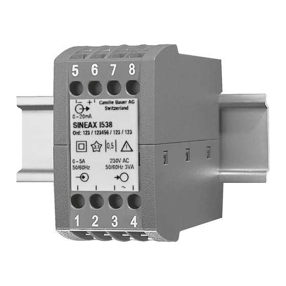
Geräte- ±10% max. [kΩ] = 5 6 7 8 20 mA Rückseite – bei Spannungsausgang den Wert Camille Bauer AG Hersteller Switzerland 0–20mA min. [kΩ] ≥ SINEAX I 538 10 mA Ord: 123 / 123456 / 123 / 123... -
Page 4: Inbetriebnahme Und Wartung
6. Inbetriebnahme und Wartung 8. Gerätezulassung Hilfsenergie und Messeingang einschalten. Der Messumformer ist wartungsfrei. Germanischer Lloyd Zulassung Zertifi kat Nr.: 12 259-98 HH 7. Demontage-Hinweis CSA geprüft für USA und Kanada fi le-nr. 204767 Messumformer gemäss Bild 7 von Tragschiene abnehmen. 9. -
Page 5: A Lire En Premier, Ensuite
Mode d’emploi Convertisseur de mesure pour courant alternatif SINEAX I 538 Les conseils de sécurité qui doivent impérativement être Sortie de mesure observés sont marqués des symboles ci-contre dans le Courant continu: 0 - 1 à 0 - 20 mA resp. live-zéro présent mode d’emploi: 0,2 - 1 à... -
Page 6: Fixation
5 6 7 8 variable ±10% H = Alimentation d’appareil auxiliaire [V] H [V] – 12 V Camille Bauer AG Fabricant Switzerland max. [kΩ] = 0–20mA 20 mA SINEAX I 538 Ord: 123 / 123456 / 123 / 123 –... -
Page 7: Mise En Service Et Entretien
6. Mise en service et entretien 9. Croquis d’encombrement 112,5 Enclencher l’alimentation auxiliaire et l’entrée de mesure. Le convertisseur de mesure ne nécessite pas d’entretien. 5 6 7 8 7. Indication pour le démontage Démonter le convertisseur du rail support selon Fig. 7. 1 2 3 4 114,1 Fig. -
Page 8: Read Fi Rst And Then
Operating Instructions Transducer for AC current SINEAX I 538 Measuring output Safety precautions to be strictly observed are marked with following symbols in the Operating Instructions DC current: 0 - 1 to 0 - 20 mA resp. live-zero 0.2 - 1 to 4 - 20 mA Burden voltage: 15 V External resistance:... -
Page 9: Mounting
Test marks on 5 6 7 8 sensibility ±10% device rear side H = Power supply [V] Camille Bauer AG Manufacturer Switzerland H [V] – 12 V 0–20 mA max. [kΩ] = SINEAX I 538 20 mA Ord: 123 / 123456 / 123 / 123 Works No. -
Page 10: Commissioning And Maintenance
6. Commissioning and maintenance 9. Dimensional drawing 112.5 Switch on the power supply and the measuring input. No maintenance is required. 5 6 7 8 7. Releasing the transducer Release the transducer from a top-hat rail as shown in Fig. 7. 1 2 3 4 114.1 Fig. -
Page 11: Konformitätserklärung
10. Konformitätserklärung / Certifi cat de conformité / Declaration of conformity...
Need help?
Do you have a question about the 136590 and is the answer not in the manual?
Questions and answers