Table of Contents
Advertisement
Quick Links
Advertisement
Table of Contents

Subscribe to Our Youtube Channel
Related Manuals for Maxcess MAGPOWR LC500G


Summary of Contents for Maxcess MAGPOWR LC500G
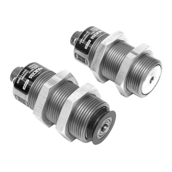
- Page 1 LC500G Load Cell Instruction Manual LC500G LC500G-S1 MI 850A296 1 E...
- Page 2 All of the information herein is the exclusive proprietary property of Maxcess International, and is disclosed with the understanding that it will be retained in confidence and will neither be duplicated nor copied in whole or in part nor be used for any purpose other than for that disclosed.
-
Page 3: Product Overview
3. The part of the shaft that is inserted into the load cell Snap ring PN 29L700A2851 also acts as an overload stop for the load cell. Bearing PN 29L30A391 Shaft assembly parts can also be purchased from Maxcess. Figure 1. Pulley shaft dimensions www.maxcessintl.com LC500G Load Cell MI 850A296 1E... -
Page 4: Symbols Used
SAFETY Safety The content of these instructions must be read and followed. All national, state, and local requirements for installation, accident prevention and environmental protection must be followed. To ensure safe and problem free installation of the load cell device, the load cell must be properly transported and stored, professionally installed and placed in operation. -
Page 5: Basic Safety Information
SAFETY Basic safety information Proper use The load cell devices are intended to be used on machines or systems to monitor the tension in a strand via a single strand pulley attached to the load cell. Indoor operation. Improper use Operation outside the technical specifications ... -
Page 6: Installation
INSTALLATION Installation CAUTION – Possible damage to load cell. Do not hammer on the load cell. CAUTION – Possible damage to load cell. Do not disassemble the load cell. There are no serviceable parts inside. WARNING – Danger of injury from crushing. Maintenance and repair tasks on the load cell device must be performed only when the machine has been stopped and has been secured from being turned on again. -
Page 7: Maintenance And Specifications
MAINTENANCE AND SPECIFICATIONS Maintenance There is no maintenance required for the LC500G. Specifications Figure 3. LC500G dimensions – inches [millimeters] with pulley without pulley Gage Resistance 350 ohm Gage Type Metal foil, full bridge Excitation Voltage 10 VDC nominal Output Signal 21 mVDC nominal at full load rating Operating Temperature -30 to 95 °C [ -22 to 203 °F]... - Page 8 AND AFRICA AND SE ASIA Tel +1.405.755.1600 Tel +86.756.881.9398 Tel +91.22.27602633 Tel +81.43.421.1622 Tel +49.6195.7002.0 asia@maxcessintl.com Fax +1.405.755.8425 Fax +86.756.881.9393 Fax +91.22.27602634 Fax +81.43.421.2895 Fax +49.6195.7002.933 www.maxcess.asia sales@maxcessintl.com info@maxcessintl.com.cn india@maxcessintl.com japan@maxcessintl.com sales@maxcess.eu www.maxcessintl.com www.maxcessintl.com.cn www.maxcess.in www.maxcess.jp www.maxcess.eu © 2019 Maxcess...
Need help?
Do you have a question about the MAGPOWR LC500G and is the answer not in the manual?
Questions and answers