Table of Contents
Advertisement
Quick Links
Advertisement
Table of Contents

Related Manuals for CYBEX 525AT


Summary of Contents for CYBEX 525AT
- Page 1 525AT Arc Trainer Owner's Manual Part Number 1008575-0001 AB...
- Page 3 User and Service Documents Link Operation Manuals and other Product Information available at https://www.lftechsupport.com/web/document-library/documents https://www.lftechsupport.com/web/document-library/documents https://www.lftechsupport.com/web/document-library/documents https://www.lftechsupport.com/web/document-library/documents https://www.lftechsupport.com/web/document-library/documents https://www.lftechsupport.com/web/document-library/documents Trobareu el manual de funcionament i altra informació de producte a https://www.lftechsupport.com/web/document-library/documents Mae Llawlyfrau Gweithredu a Gwybodaeth Arall am Beiriannau ar gael yn https://www.lftechsupport.com/web/document-library/documents Die Betriebsanleitung und andere Produktinformationen erhalten Sie unter https://www.lftechsupport.com/web/document-library/documents...
-
Page 4: Table Of Contents
Cybex logo are registered trademarks of Cybex International, Inc. DISCLAIMER: Cybex International, Inc. makes no representations or warranties regarding the contents of this manual. We reserve the right to revise this document at any time or to make changes to the product described within it without notice or obligation to notify any person of such revisions or changes. -
Page 5: Getting Started
Please take special note of the following safety instructions and important points prior to choosing a location and beginning assembly of the product. Warning: Health-related injuries may result from incorrect or excessive use of exercise equipment. Cybex International, Inc. STRONGLY recommends seeing a physician for a complete medical exam before undertaking an exercise program, particularly if the user has a family history of high blood pressure or heart disease, is over the age of 45, smokes, has high cholesterol, is obese, or has not exercised regularly in the past year. - Page 6 Warning labels are shipped with every product and should be installed before product is used. Cybex International, Inc. is not responsible for missing or damaged warning labels. • Health and Environmental Regulations Warning - This product may contain chemicals known to the State of California to cause cancer, birth defects, or other reproductive harm.
-
Page 7: Sécurité
Prêtez une attention toute particulière aux instructions de sécurité ci-dessous avant de choisir un emplacement et de commencer à assembler votre CYBEX INTERNATIONAL INC. . AVERTISSEMENT: Une utilisation incorrecte ou excessive de l'appareil peut entraîner des blessures. CYBEX INTERNATIONAL INC. recommande VIVEMENT aux utilisateurs de passer un examen médical complet avant d'entamer un programme d'entraînement, et tout particulièrement dans les cas suivants : antécédents... - Page 8 • Si certaines étiquettes d'avertissement sont manquantes ou endommagées, contactez immédiatement le Service à la clientèle. Nous vous en fournirons de nouvelles. Les étiquettes d'avertissement sont expédiées avec les appareils et doivent être installées avant utilisation de ces derniers. Cybex International, Inc. n'est pas responsable des étiquettes manquantes ou endommagées.
-
Page 9: Cautions
Warnings and Cautions Warning labels indicate a potentially hazardous situation that could result in serious injury or death if the precautions are not observed. Caution labels indicate a potentially hazardous situation that could result in serious injury or damage to machine if the precautions are not observed. -
Page 10: Placement
Label, Warning, Access Tray, Left 770A-331-E Label, Warning, Access Tray, Left, Canadian 770A-332-X Label, Warning, Access Tray, Right 770A-332-E Label, Warning, Access Tray, Right, Canadian 525AT-400 Label, Warning, Disconnect Power 525AT-401 Label, Warning, Disconnect Power 525AT-402 Label, Warning, Disconnect Power DE-17155-X... -
Page 11: Setup
Setup Read the entire manual before setting up the unit. Electrical Power Requirements CYBEX INTERNATIONAL INC. require an AC power supply according to the electrical configurations listed in the chart below. Supply Voltage Frequency (Hz) Equipment Rated Current (Amps) 50 / 60... -
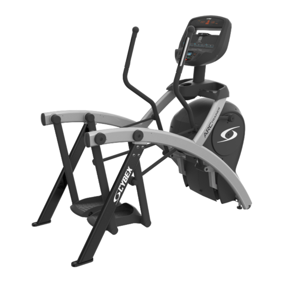
Page 12: Product Overview
Product Overview Product Features Item Description Console Accessory Trays Cup Holder Contact Heart Rate Sensors Leg Levelers Mounting and Dismounting the Arc Trainer To mount, step one foot at a time atop each of the foot plates. If necessary, stabilize your body by grasping the frame, the stationary handles (if available), or the moving handles (if available). -
Page 13: Assembly
Assembly Assembly Procedure Two people will be required for this procedure. Tip: Read and understand all instructions thoroughly before assembling this unit. Check all items carefully. If there is damage, see the Customer Service section of this manual for proper procedure to return, replace, or reorder parts. - Page 14 Hardware Item Description Qty. Flange Spacer 3/16” Allen Wrench 7/32” Allen Wrench BHSCS .375-16 × 2.25” Grommet, Nylon Locknut, .375-16 Nylon Washer, Flat .281 ID × .500 OD × .062” Screw, Pan Head Phillips, #6 x .50” Screw, Pan Head Phillips, 8-16 × .50” Tap Sc 10-12 ×...
- Page 15 Tools Required • Stubby Phillips screwdriver • 3/16” Allen wrench (included) • 7/32” Allen wrench (2) (included) • 9/16” Open end wrench Lift and Move Unit 1. Remove lag bolts and shipping supports. Keep package material on linkage arms at this time. This will protect the paint from scratching during assembly.
- Page 16 Install Console Assembly 1. Place the console into position on the frame. Do not pinch cables while lowering the console. Item Description Qty. Locknuts Console Frame Bolts Upper Heart Rate Cable Lower Heart Rate Cable Upper Display Cable Lower Display Cable 2.
- Page 17 Item Description Qty. Accessory Tray Top Accessory Tray Base Screw, Pan Head Phillips, 8-16 x .50" Install Accessory Tray Bottom 1. Install the grommet to the frame. Item Description Qty. Grommet, Nylon, Long Frame 2. Install screws securing the accessory tray bottom to the accessory tray top using a Phillips screwdriver. 3.
- Page 18 Remove Left and Right Handle Assembly The left and right handle assemblies are shipped in rotated positions. The handle assemblies must be removed and rotated 180 degrees for proper setup and assembly. Item Description Qty. Left Handle Assembly Right Handle Assembly 1.
- Page 19 7. Remove a screw and washer from the right handle assembly using two 7/32” Allen wrenches. Item Description Qty. Washer Screw Right Handle Pivot Pin Assembly 8. Slide pivot pin assembly out and remove right handle assembly. 9. Rotate right handle assembly 180 degrees. 10.
- Page 20 Item Description Qty. Right Linkage Rod Right Arm Flange Spacer Linkage Rod Cap Washer Loctite Screw 2. Place a drop of Loctite onto the screw. 3. Install the screw, washer, linkage rod cap, and flange spacer using a 3/16” Allen wrench. 4.
- Page 21 3. Repeat steps to install heart rate cable on opposite handle. Install Foot Pads Have one person lift the unit while a second person places a foot pad under each of the two back feet. Item Description Qty. Foot pads Visually Inspect Unit 1.
-
Page 22: Testing Operation
3. Grasp the other side of the frame and slowly lift the rear foot off the floor. Lower rear foot to the floor. Make note of either rear foot lifting off the floor easier than the other. If both rear feet lift off the floor evenly, secure both leveling foot jam nuts against the frame post using a 9/16” open-end wrench. -
Page 23: Time And Date Confirmation
3. Hold the handrails to steady self while stepping into the foot plates. 4. Begin striding. 5. Verify lower heart rate cable is not rubbing on handle during operation. 6. Press Quick Start. 7. Run unit through full resistance range. First press the Resistance + key until unit reaches its highest load (the display will show 100). -
Page 24: Operation
Operation Intended Use The intended commercial use of this machine is to aid exercise and improve general physical fitness. Individual Human Power Versus Mechanical Power Warning: Power difference. The individual human power which is required to carry out an exercise can be different than the mechanical power displayed. - Page 25 INCLINE UP Adjust Incline up. INCLINE DOWN Adjust Incline down. RESISTANCE UP Adjust Resistance +up. RESISTANCE DOWN Adjust Resistance -down. VOLUME UP Adjust Volume up. VOLUME DOWN Adjust Volume down. Adjust Time, Level, Weight, or Workout up UP KEY A/V - Channel UP Adjust Time, Level, Weight, or Workout down DOWN KEY A/V - Channel DOWN...
-
Page 26: Console Display
Console Display LED Display Left enunciator Displays Time, BPM, or Weight. Left data readout Displays value of Time, BPM, or Weight. Bar graph Displays workout profiles and setup options. Right enunciator Displays Calories, SPM, or Cal/Hour. Right data readout Displays value of Calories, SPM, or Cal/Hour. User Controls Incline keys Resistance keys... -
Page 27: Mount And Dismount
Incline display Volume keys Enter key Quick Start key Display option key Up/Down keys Workouts key Headphone jack Resistance display STOP key Displays Incline and Resistance are shown in the LED displays. Keys User controls for Incline, Quick Start, Workouts, Resistance, Volume, Scan, STOP, Setup, Enter and Up/Down. -
Page 28: Quick Operation Guide
Quick Operation Guide Maximum user weight is 400 lbs. (181 kg). The following is a quick overview of the operation of the unit. 1. Verify foot plates are completely stopped. 2. Grasp handrail and step carefully onto foot plates. Begin striding. 3. - Page 29 3. Verify foot plates are completely stopped. 4. Grasp handrail and step carefully onto foot plates. Begin striding. 5. Select Quick Start or WORKOUTS. If Quick Start is selected, The console will beep for one second to signal start of workout and enter Active Mode.
-
Page 30: Safety Sentry
Safety Sentry Safety Sentry uses display feedback (speed signal or key presses) to determine user presence. If a user is not detected within 10 seconds, the display beeps and inquires PEdl?. Resume striding or press any key within a pre-selected time to resume workout. Workout Selection Choose from Quick Start or eight workout choices. -
Page 31: Heart Rate Indicator
Heart Rate Indicator Contact Heart Rate Lightly hold hand grips on the handlebar ensuring that hands are clean and contact both the front and back sensors of each grip. A heart rate will display in typically 30 seconds or less. Factors that interfere with heart rate signal: •... -
Page 32: Service And Technical Data
• Locate the product in a cool, dry place. • Clean the display console and all exterior surfaces with an approved or compatible cleaner (see CYBEX INTERNATIONAL INC. Approved Cleaners) and a microfiber cloth. • Long fingernails may damage or scratch the surface of the console; use the pad of the finger to press the selection buttons on the console. -
Page 33: Troubleshooting The Polar Heart Rate Chest Strap
Gym Wipes are large, durable pre-moistened wipes to use on the equipment before and after workouts. Use Gym Wipes on the equipment for at least 2 minutes for general disinfection purposes. Contact Customer Support Services to order these cleaners (1-800-351-3737 or email: customersupport@lifefitness.com). - Page 34 Description Qty. Screw Front Access Cover 2. Remove access cover. Warning: Burn hazard. Do not touch flywheel until cool. Inspect Drive Belts There are two drive belts that may become loose, worn or cracked. Unless the belts have been removed and not replaced properly, it is unlikely the belts will come loose or need to be re-tensioned.
-
Page 35: How To Obtain Product Service
How to Obtain Product Service 1. Verify the symptom and review the operating instructions. The problem may be unfamiliarity with the product and its features and workouts. 2. Locate and write down the serial number of the unit which is located on the front of the unit. Write down the software version if possible. -
Page 36: Specifications
Specifications Designed Use Heavy / Commercial Class SA Maximum User Weight 400 lbs. / 181 kg Drive Type Belt / Alternator Incline Levels 0-20 Resistance Levels 0-80 Stride Length 24” (61 cm) fixed length Power Requirements 100-120 VAC, 3.0 A, 1-Phase or 200-240 VAC, 2.5 A, 1-Phase. Heart Rate Monitoring Systems Polar®... -
Page 37: Appendix - Workout Overviews
Appendix - Workout Overviews 1 - Weight Loss 1 The Weight Loss 1 workout is a five-minute core workout designed for low to medium intensity training that the user can sustain for an extended period of time. It builds from a low intensity baseline to include short bursts of higher resistance while the elevation increases by fifty percent for two-minutes. - Page 38 Time 1:00 1:00 1:00 1:00 1:00 Warm Up Core Segments Cool Down Page 38 of 53...
- Page 39 2 - Weight Loss 2 The Weight Loss 2 workout is a five-minute core workout that begins at a low intensity level and incrementally increases both resistance and elevation until peaking after three-minutes and remains at that level for one-minute before ramping back down to the initial level.
- Page 40 Time 1:00 1:00 1:00 1:00 1:00 Warm Up Core Segments Cool Down Page 40 of 53...
- Page 41 3 - Weight Loss 3 The Weight Loss 3 workout is a three-minute thirty-second core workout designed to give the user an intense workout. Users will experience moderate resistance and elevation at the beginning to simulate the start of a climb and will crest at peak elevation gain and difficult resistance after two-minutes.
- Page 42 Time Warm Up Core Segments Cool Down Page 42 of 53...
- Page 43 4 - Cardio 1 The Cardio 1 workout is a four-minute core workout designed for medium intensity workouts. Users will experience intervals of moderate resistance and elevation at the beginning to simulate the start of a climb and greater resistance and steeper elevation after two-minutes. The resistance then returns to the preliminary level and the core workout repeats itself for the next interval.
- Page 44 Time 2:00 2:00 Warm Up Core Segments Cool Down Page 44 of 53...
- Page 45 5 - Cardio 2 The Cardio 2 workout is a two-minute core workout utilizing a 1:1 work to rest ratio. It is designed to improve both aerobic and anaerobic capabilities as users will face a high level of resistance for one minute followed by a one-minute recuperation period before performing the work interval again.
- Page 46 Time 1:00 1:00 Warm Up Core Segments Cool Down Page 46 of 53...
- Page 47 6 - Cardio 3 The Cardio 3 workout is designed to maintain a high total demand with two-minutes with high resistance and low elevation and two minutes at medium resistance with higher elevation for a total four-minute core workout. The prolonged exertion period takes advantage of the long term energy stores and total aerobic capability when associated with speeds that require a high sustained cardiovascular demand.
- Page 48 Time 2:00 2:00 Warm Up Core Segments Cool Down Page 48 of 53...
- Page 49 7 - Strength 1 The Strength 1 workout uses a 1:2 work to rest ratio. It is designed for high resistance training with longer rest periods than the 1:1 workout. Users will face a high level of resistance for thirty-seconds followed by a one minute recuperation period before performing the interval again.
- Page 50 Time Warm Up Core Segments Cool Down Page 50 of 53...
- Page 51 8 - Strength 2 The Strength 2 workout is designed with the specific goal of raising the users’ lactic acid threshold. The workout uses a 1:3 work to rest ratio with fifteen-second intervals for maximum power development and forty-five second rest periods for recuperation.
- Page 52 Time Warm Up Core Segments Cool Down Page 52 of 53...
- Page 54 Columbia Center III - 9525 West Bryn Mawr Ave, Rosemont, IL 60018 • 800-351-3737 • 847-288-3700 • FAX 800-216-8893 www.cybexintl.com...
Need help?
Do you have a question about the 525AT and is the answer not in the manual?
Questions and answers
ТECHNOGYM беговая дорожка ошибка 12не могу найти ответ спасибо
ДОБРЫЙ ДЕНЬ НУЖНО ФОТО НИЖНЕЙ ПЛАТЫ cybex525at