Table of Contents
Advertisement
Quick Links
CAN-PCIe/200
Passive CAN-Interface Board
CAN-PCIe/200
Vahrenwalder Str. 207 • 30165 Hannover • Germany
Phone: +49 (0) 511 3 72 98-0 • Fax: +49 (0) 511 3 72 98-68
for PCI Express
Hardware Manual
to Product
Hardware Manual • Doc. No.: C.2042.21 / Rev. 1.5
esd electronics gmbh
http://www.esd.eu
®
CAN-PCIe/200-2
(C.2042.04)
C.2042.02,
C.2042.04
Page 1 of 28
Advertisement
Table of Contents

Related Manuals for ESD CAN-PCIe/200


Summary of Contents for ESD CAN-PCIe/200
- Page 1 CAN-PCIe/200 Hardware Manual • Doc. No.: C.2042.21 / Rev. 1.5 Page 1 of 28 esd electronics gmbh Vahrenwalder Str. 207 • 30165 Hannover • Germany http://www.esd.eu Phone: +49 (0) 511 3 72 98-0 • Fax: +49 (0) 511 3 72 98-68...
- Page 2 design.
- Page 3 Added new chapter 'CAN Troubleshooting Guide' Added new Declaration of Conformity 2012-11-30 Updated chapter 'Order Information' 2012-12-03 Name of product corrected : CAN-PCIe/200 Safety Instructions ans Trademark Notices revised 'Electrical isolation' entry revised 2014-06-25 chapter updated Declaration of Conformity updated...
- Page 4 This NOTICE statement contains the general mandatory sign and gives information that must be heeded and complied with for a safe use. INFORMATION INFORMATION Notes to point out something important or useful. Page 4 of 28 Hardware Manual • Doc. No.: C.2042.21 / Rev. 1.5 CAN-PCIe/200...
-
Page 5: Safety Instructions
● The device is a built-in component. It is essential to ensure that the device is mounted in a way that cannot lead to endangering or injury of persons or damage to objects. ● Do not use damaged or defective cables to connect the CAN-PCIe/200 and follow the CAN wiring hints in chapter: "Correct Wiring of Electrically Isolated CAN Networks". - Page 6 Application Programming Interface Controller Area Network Central Processing Unit CAN in Automation Hardware Input/Output Least Significant Bit Most Significant Bit n.a. not applicable Operating System Software Development Kit Page 6 of 28 Hardware Manual • Doc. No.: C.2042.21 / Rev. 1.5 CAN-PCIe/200...
-
Page 7: Table Of Contents
7.1 Termination.......................... 23 Electrical Grounding......................24 Short Circuit in CAN Wiring....................24 CAN_H/CAN_L-Voltage ......................24 CAN Transceiver Resistance Test..................25 Support by esd........................25 Declaration of Conformity......................26 Order Information........................27 CAN-PCIe/200 Hardware Manual • Doc. No.: C.2042.21 / Rev. 1.5 Page 7 of 28... -
Page 8: Overview
+12 V= Figure 1: Block circuit diagram of CAN-PCIe/200 The CAN-PCIe/200 is a passive CAN interface board for PCI Express with one, or optionally two CAN interfaces. The ISO 11898-2 CAN interface allows a maximum data transfer rate of 1 Mbit/s. Among many other features of the CAN interfaces, the baud rate can be set by software. -
Page 9: Pcb View With Connectors
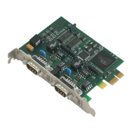
Overview 1.2 PCB View with Connectors Figure 2: PCB view of CAN-PCIe/200-2 with 2 CAN interfaces On CAN-PCIe/200-1 (C.2042.02) the interface CAN Net 1 is not equipped. See also page 15 for signal assignment of the CAN connectors. NOTICE Read chapter “Hardware Installation” on page 10, before you start with the installation of... -
Page 10: Hardware Installation
Switch off your system and all connected peripheral devices (monitor, printer, etc.). Switch off the connected CAN devices. Discharge your body as described above. Disconnect the system from the mains. Make sure that no risk arises from the system into which the CAN-PCIe/200 shall be inserted. DANGER Hazardous Voltage Risk of electric shock due to unintentional contact with uninsulated live parts with high voltages. - Page 11 Please note that the CAN bus has to be terminated at both ends! Additionally the CAN_GND signal has to be connected to earth at exactly one point. For easier wiring esd offers termination connectors with an earth connector (4.8 mm fast-on, male).
-
Page 12: Technical Data
CAN interfaces are electrically isolated via optocouplers and DC/DC- isolation of the converters against each other and against the PCIe bus potentials CAN interface against other units Table 3: Data of the CAN interface Page 12 of 28 Hardware Manual • Doc. No.: C.2042.21 / Rev. 1.5 CAN-PCIe/200... -
Page 13: Software Support
- 30 MB free HD drive space - esd CAN driver installed As part of the esd software development kit (CAN SDK) of the NTCAN-API the CAN Tools are included in delivery of the CAN-CD. The CAN SDK can also be downloaded free-of-charge from the esd website. -
Page 14: Front Panel View With Led-Display
Front Panel View with LED-Display 4. Front Panel View with LED-Display The CAN-PCIe/200 is equipped with four green LEDs located in the front panel. Figure 3: Front panel view of CAN-PCIe/200-2 Name Function Colour Display function (LED on) ADU-CS green... -
Page 15: Connector Assignments
CAN physical layer Shield ... shielding (connected with the chassis ground of the 9-pin DSUB connector) reserved ... reserved for future applications, do not connect! CAN-PCIe/200 Hardware Manual • Doc. No.: C.2042.21 / Rev. 1.5 Page 15 of 28... -
Page 16: Correct Wiring Of Electrically Isolated Can Networks
Therefore the practical maximum number of nodes, bus length and stub length are typically much lower. esd has concentrated her recommendations concerning CAN wiring on the specifications of the ISO 11898-2. Thus this wiring hints forgoes to describe the special features of the derived standards CANopen, ARINC825, DeviceNet and NMEA2000. -
Page 17: Heavy Industrial Environment (Double Twisted Pair Cable)
6.2 Heavy Industrial Environment (Double Twisted Pair Cable) 6.2.1 General Rules NOTICE esd only grants the compliance with directive 2014/30/EU, if the CAN wiring is carried out with single shielded double twisted pair cables that match the requirements of ISO 11898-2. -
Page 18: Device Cabling
CAN bus line via short cable stubs. This is normally realised by so called T- connectors. When using esd's CAN-T-Connector (order no.: C.1311.03) it should be noted that the shield potential of the conductive DSUB housing is not looped through this T- Connector type. -
Page 19: Light Industrial Environment (Single Twisted Pair Cable)
6.3.1 General Rules NOTICE esd only grants the compliance with directive 2014/30/EU, if the CAN wiring is carried out with single shielded double twisted pair cables that match the requirements of ISO 11898-2. See previous chapter: 'Heavy Industrial Environment (Double Twisted Pair Cable)'. -
Page 20: Cabling
9-pin DSUB-termination connectors with integrated termination resistor and male and ● female contacts are available from esd (order no. C.1303.01). DSUB termination connectors with male contacts (order no. C.1302.01) or female contacts ● (order no. C.1301.01) and additional functional earth contact are available, if CAN termination and grounding of CAN_GND is required. -
Page 21: Electrical Grounding
5000 Table 5: Recommended cable lengths at typical bit rates (with esd-CAN interfaces) Optical couplers are delaying the CAN signals. esd modules typically reach a wire length of ● 37 m at 1 Mbit/s within a proper terminated CAN network without impedance disturbances like e.g. -
Page 22: Examples For Can Cables
Correct Wiring of Electrically Isolated CAN Networks 6.6 Examples for CAN Cables esd recommends the following two-wire and four-wire cable types for CAN network design. These cable types are used by esd for ready-made CAN cables, too. 6.6.1 Cable for light industrial Environment Applications (Two-Wire) -
Page 23: Can Troubleshooting Guide
- there are no open circuits in CAN_H or CAN_L wiring - your bus system has two terminating resistors (one at each end) and that they are 120 Ω each. CAN-PCIe/200 Hardware Manual • Doc. No.: C.2042.21 / Rev. 1.5 Page 23 of 28... -
Page 24: Electrical Grounding
(see figure at previous page). 4. Measure the DC voltage between CAN_L and CAN_GND (see figure at previous page). Normally the voltage should be between 2.0 V and 3.0 V. Page 24 of 28 Hardware Manual • Doc. No.: C.2042.21 / Rev. 1.5 CAN-PCIe/200... -
Page 25: Can Transceiver Resistance Test
If you have executed the fault diagnostic steps of this troubleshooting guide and you even can not find a solution for your problem our support department will be able to assist. Please contact our support via email at support@esd.eu or by phone +49-511-37298-130. CAN-PCIe/200 Hardware Manual •... -
Page 26: Declaration Of Conformity
Declaration of Conformity 8. Declaration of Conformity Page 26 of 28 Hardware Manual • Doc. No.: C.2042.21 / Rev. 1.5 CAN-PCIe/200... -
Page 27: Order Information
J1939 Stack for esd CAN-Hardware - RTX object C.1130.12 (Object) code - includes esd CAN driver licence for RTX * For detailed information about the driver availability for your special operating system, please contact our sales team. Table 6: Order information CAN-PCIe/200 Hardware Manual •... - Page 28 Order Information PDF Manuals Manuals are available in English and usually in German as well. Available manuals are listed in the following table. Please download the manuals as PDF documents from our esd website www.esd.eu for free. Manuals Order No.
Need help?
Do you have a question about the CAN-PCIe/200 and is the answer not in the manual?
Questions and answers