Table of Contents
Advertisement
Quick Links
CAN-PCIe/200
Passive CAN-Interface Board
for PCI Express
Hardware Manual
to Product C.2042.xx
CAN-PCIe/200
Seite 1 von 22
Hardware Manual • Doc. No.: C.2042.21 / Rev. 1.2
esd electronic system design gmbh
Vahrenwalder Str. 207 • 30165 Hannover • Germany
www.esd-electronics.com • Fax: 0511/37 29 8-68
Phone: 0511/37 29 80 • International: +49-5 11-37 29 80
Advertisement
Table of Contents

Subscribe to Our Youtube Channel
Related Manuals for ESD CAN-PCIe/200


Summary of Contents for ESD CAN-PCIe/200
- Page 1 Seite 1 von 22 Hardware Manual • Doc. No.: C.2042.21 / Rev. 1.2 esd electronic system design gmbh Vahrenwalder Str. 207 • 30165 Hannover • Germany www.esd-electronics.com • Fax: 0511/37 29 8-68 Phone: 0511/37 29 80 • International: +49-5 11-37 29 80...
- Page 2 gmbh.
- Page 3 The changes in the user’s manual listed below affect changes in the firmware as well as changes in the description of the facts only. Chapter Changes versus previous version Product name changed from CAN-PCIe/2000 to CAN-PCIe/200. Footer and page numbers changed. Technical details are subject to change without notice. Seite 3 von 22 CAN-PCIe/200 Hardware Manual •...
- Page 4 This page is intentionally left blank. Seite 4 von 22 CAN-PCIe/200 Hardware Manual • Doc. No.: C.2042.21 / Rev. 1.2...
-
Page 5: Table Of Contents
7.4 CAN Transceiver Resistance Test ..........22 CAN-PCIe/200 Seite 5 von 22 Hardware Manual •... - Page 6 This page is intentionally left blank. Seite 6 von 22 CAN-PCIe/200 Hardware Manual • Doc. No.: C.2042.21 / Rev. 1.2...
-
Page 7: Overview
+12 V= Fig. 1.1: Block circuit diagram of CAN-PCIe/200 The CAN-PCIe/200 is a passive CAN interface board for PCI Express with one, or optionally two CAN interfaces. The ISO 11898-2 CAN interface allows a maximum data transfer rate of 1 Mbit/s. Among many other features of the CAN interfaces, the baud rate can be set by software. -
Page 8: Pcb View With Position Of The Connectors
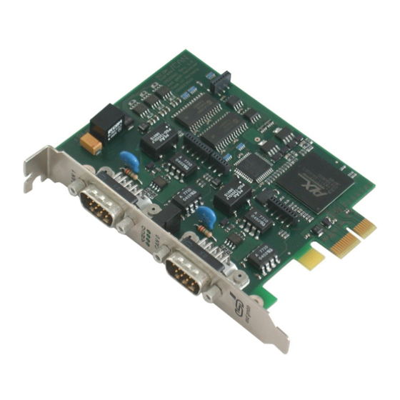
Overview 1.2 PCB View with Position of the Connectors Fig. 1.2: PCB view of CAN-PCIe/200-2 with 2 CAN interfaces Seite 8 von 22 CAN-PCIe/200 Hardware Manual • Doc. No.: C.2042.21 / Rev. 1.2... -
Page 9: Hardware-Installation
Use the screw you removed from the slot cover in step 5. Replace the PC cover. Secure the cover with the screws you removed in step 4. CAN-PCIe/200 Seite 9 von 22 Hardware Manual • Doc. No.: C.2042.21 / Rev. 1.2... - Page 10 Please note that the CAN bus has to be terminated at both ends! esd offers special T- connectors and terminator connectors. Additionally the CAN_GND signal has to be connected to earth at exactly one point. For easier wiring the termination connectors are equipped with an earth connector (4.8 mm fast-on, male).
-
Page 11: Technical Data
3.2 PCI Express Interface PCIe Endpoint PEX8311 PCIe port compliant with PCI Express Specification R1.0a Connector x1 PCI Express card edge socket Table 3.2: PCI Express data CAN-PCIe/200 Seite 11 von 22 Hardware Manual • Doc. No.: C.2042.21 / Rev. 1.2... -
Page 12: Can Interface
Software drivers are available for Windows, Linux and QNX. Drivers for other operating systems are available on request. For detailed information about drivers for other operating systems, please contact our support (support@esd-electronics.com). The CAN-API is described in the manual: "CAN-API, Part 1: Function description"... -
Page 13: Order Information
Technical Data 3.5 Order Information Type Description Order No. CAN-PCIe/200-1 1 x CAN, ISO11898-1, ISO11898-2 C.2042.02 CAN-PCIe/200-2 2 x CAN, ISO11898-1, ISO11898-2 C.2042.04 CAN-DRV-LCD Object licence for Windows and Linux incl. CD-ROM C.1101.02 CAN-PCIe/200-Vx VxWorks object licence C.2042.55 Hardware manual in English CAN-PCIe/200-ME C.2042.21... -
Page 14: Front Panel View With Led Display
LED Display 4. Front Panel View with LED Display The CAN-PCIe/200 is equipped with four green LEDs located in the front panel. Fig. 4.1: Front panel view Display function (LED on) Name Function Colour ADU-CS green reserved CAN1-IRQ green Interrupt in CAN Net 1 -... -
Page 15: Connector Assignment Of The Can Bus Interface
CAN layer (CAN_GND) ... optional reference potential of the local physical CAN layer reserved ... reserved for future applications Shield... shielding CAN-PCIe/200 Seite 15 von 22 Hardware Manual • Doc. No.: C.2042.21 / Rev. 1.2... -
Page 16: Correctly Wiring Electrically Isolated Can Networks
CAN_GND CAN_H n.c. n.c. n.c. n.c. n.c. n.c. connector case connector case earth (PE) n.c. = not connected Figure: Structure and connection of wire Seite 16 von 22 CAN-PCIe/200 Hardware Manual • Doc. No.: C.2042.21 / Rev. 1.2... - Page 17 Earthing CAN_GND has to be conducted in the CAN wire, because the individual esd modules are electrically isolated from each other! CAN_GND has to be connected to the earth potential (PE) at exactly one point in the net! ...
- Page 18 Optical couplers are delaying the CAN signals. By using fast optical couplers and testing each board at 1 Mbit/s, however, esd CAN guarantee a reachable length of 37 m at 1 Mbit/s for most esd CAN modules within a closed net without impedance disturbances like e.g. longer dead-end feeders.
- Page 19 Order No.: 56202251 Germany CB 627 (1 x 2 x 0.25 mm²) Order No.: 06272251 (UL appr.) www.sab-brockskes.de Note: Completely configured CAN wires can be ordered from esd. CAN-PCIe/200 Seite 19 von 22 Hardware Manual • Doc. No.: C.2042.21 / Rev. 1.2...
-
Page 20: Can-Bus Troubleshooting Guide
- there are no open circuits in CAN_H or CAN_L wiring - your bus system has two terminating resistors (one at each end) and that they are 120 each. Seite 20 von 22 CAN-PCIe/200 Hardware Manual • Doc. No.: C.2042.21 / Rev. 1.2... -
Page 21: Can_H/Can_L Voltage
3. Connect Shield wire to ground. The resistance should be higher than 1 M . If it is lower, please search for additional grounding of the shield wires. CAN-PCIe/200 Seite 21 von 22 Hardware Manual • Doc. No.: C.2042.21 / Rev. 1.2... -
Page 22: Can Transceiver Resistance Test
CAN transceiver is probably faulty. Ω Ω CAN-node CAN_H CAN_L CAN- Transceiver CAN_GND Disconnect Power CAN ! Disconnect Power ! Figure: Simplified diagram of a CAN node Seite 22 von 22 CAN-PCIe/200 Hardware Manual • Doc. No.: C.2042.21 / Rev. 1.2...
Need help?
Do you have a question about the CAN-PCIe/200 and is the answer not in the manual?
Questions and answers