
Subscribe to Our Youtube Channel
Related Manuals for ESD CAN-M.2/402-2-FD


Summary of Contents for ESD CAN-M.2/402-2-FD
- Page 1 CAN-M.2/402-2-FD M.2 Card with 2 CAN FD Interfaces Hardware Manual to Product C.2074.64 CAN-M.2/402-2-FD Hardware Manual Doc.-Nr.: C.2074.21 /-Rev 1.0 Page 1 of 32...
- Page 2 design.
- Page 3 The changes in the document listed below affect changes in the hardware as well as changes in the description of the facts, only. Rev. Chapter Changes versus previous version Date First English manual 2020-08-27 Technical details are subject to change without further notice. CAN-M.2/402-2-FD Hardware Manual Doc.-Nr.: C.2074.21/ 1.0 Page 3 of 32...
- Page 4 This NOTICE statement contains the general mandatory sign and gives information that must be heeded and complied with for a safe use. INFORMATION INFORMATION Notes to point out something important or useful. Page 4 of 32 Hardware Manual Doc.-Nr.: C.2074.21 /Rev. 1.0 CAN-M.2/402-2-FD...
-
Page 5: Safety Instructions
● Do not use damaged or defective cables to connect the CAN-M.2/402-2-FD and follow the CAN wiring hints in chapter: "Correct Wiring of Electrically Isolated CAN Networks". - Page 6 ● The CAN-M.2/402-2-FD is intended for installation in an Embedded System or PC, with indoor use only. ● The operation of the CAN-M.2/402-2-FD in hazardous areas, or areas exposed to potentially explosive materials is not permitted.
-
Page 7: Table Of Contents
Table of Contents Safety Instructions .......................... 5 1 Overview ............................. 9 1.1 Description of CAN-M.2/402-2-FD ..................9 1.2 Glossary ..........................10 2 PCB View with Connectors and LEDs ..................11 2.1 LED Display ........................11 3 Connector Assignment ......................12 3.1 CAN Connector ........................ - Page 8 Table 6: Data of the CAN interface ....................18 Table 7: Technical data of the DSUB9 adapter ................18 Table 8: Recommended cable lengths at typical bit rates (with esd-CAN interfaces) ....25 Table 9: Order information hardware .................... 31 Table 10: Order information software ...................
-
Page 9: Overview
The optional adapter CAN-PCIeMini/402-DSUB comes with a DSUB9 connector, selectable on- board CAN termination and an adapter cable. CAN-M.2/402-2-FD is fully backwards compatible with CAN and can also be used in Classical CAN applications. The independent CAN nets are driven by the ISO 16845:2004 certified esdACC (esd Advanced CAN Core) implemented in the Intel FPGA. -
Page 10: Glossary
Operating System Software Development Kit Peripheral Component Interconnect PCIe PCI Express Insulation Displacement Connector WLAN Wireless Local Area Network WWAN Wireless Wide Area Network WPAN Wireless Personal Area Network Page 10 of 32 Hardware Manual Doc.-Nr.: C.2074.21 /Rev. 1.0 CAN-M.2/402-2-FD... -
Page 11: Pcb View With Connectors And Leds
NOTICE Read chapter “Hardware Installation” on page 15, before you start with the installation of the hardware! 2.1 LED Display The CAN-M.2/402-2-FD comes with four green LEDs, which are equipped on the top layer, Figure 2 LED name Indicator Name... -
Page 12: Connector Assignment
CAN signals of the CAN net x (x... 0, 1) CANx_GND... Reference potential of the local CAN physical layer of CAN net x (x... 0, 1) reserved ... Reserved for future applications, do not connect! Page 12 of 32 Hardware Manual Doc.-Nr.: C.2074.21 /Rev. 1.0 CAN-M.2/402-2-FD... -
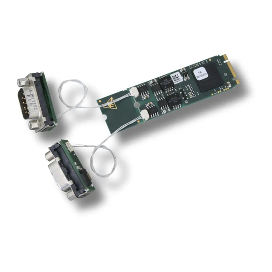
Page 13: Dsub Adapter And Adapter Cable
M.2/402-2-FD via DSUB9 connectors. The adapter CAN-PCIeMini-CAN/402-DSUB9 is not contained in the scope of delivery of ee “Order Information” on page 31 the CAN-M.2/402-2-FD. S The adapter cable CAN-PCIeMini/402-Cable and two UNC 4-40 DSUB bolts are included in the scope of delivery of CAN-PCIeMini/402-DSUB. The bolts are intended to be used with a front... -
Page 14: Connector Assignment Of Adapter
JST, SM04B-SURS-TF) is equipped on the bottom layer of the adapter. The connector assignment of the CAN cable connector on the CAN-PCIeMini/402- DSUB9 is the same as for CAN-M.2/402-2-FD, see chapter “Connector Assignment”, page 12. 4.3.3 Adapter Cable One adapter cable is included in delivery of the CAN-PCIeMini/402-DSUB9 adapter. -
Page 15: Hardware Installation
WARNING Hazardous Voltage - Risk of electric shock due to unintentional contact with uninsulated live parts with high voltages inside of the system into which the CAN-M.2/402-2-FD is to be integrated. → Disconnect all hazardous voltages (mains voltage) before opening the system. - Page 16 Close the system's case again. NOTICE Please note that the CAN bus has to be terminated at both ends! esd offers special T- connectors and termination connectors for external termination. Additionally, the CAN_GND signal has to be connected to earth at exactly one point in the CAN network.
-
Page 17: Technical Data
INFORMATION The optional CAN-M.2-80/402-2-FD comes with a maximum component hight of 1.5 mm, as required in the M.2 specification. Form factor is 2280 only! Contact our Sales Team (sales@esd.eu) for further information. CAN-M.2/402-2-FD Hardware Manual Doc.-Nr.: C.2074.21/ 1.0 Page 17 of 32... -
Page 18: Can Interfaces
The adapter is intended to be used with a front panel with 0,8 mm to 1,2 mm thickness! Don't mount the bolts into the DSUB without a front panel or additional spacers like washers, because otherwise the bolt threat might damage the DSUB. Page 18 of 32 Hardware Manual Doc.-Nr.: C.2074.21 /Rev. 1.0 CAN-M.2/402-2-FD... -
Page 19: Software Support
- 30 MB free HD drive space - esd CAN driver installed As part of the esd software development kit (CAN SDK) of the NTCAN-API the CAN Tools are included in delivery of the CAN-CD. The CAN SDK can also be downloaded free-of-charge from the esd website. -
Page 20: Correct Wiring Of Electrically Isolated Can Networks
Therefore, the practical maximum number of nodes, bus length and stub length are typically much lower. esd has concentrated her recommendations concerning CAN wiring on the specifications of the ISO 11898-2. Thus, this wiring hints forgoes to describe the special features of the derived standards CANopen, ARINC825, DeviceNet and NMEA2000. -
Page 21: Light Industrial Environment (Single Twisted Pair Cable)
7.2.1 General Rules NOTICE esd grants the EU Conformity of the product, if the CAN wiring is carried out with at least single shielded single twisted pair cables that match the requirements of ISO 11898-2. Single shielded double twisted pair cable wiring as described in chapter 7.3 ensures the EU Conformity as well. -
Page 22: Cabling
● 9-pin DSUB-termination connectors with integrated termination resistor and male and female contacts are available from esd (order no. C.1303.01). ● DSUB termination connectors with male contacts (order no. C.1302.01) or female contacts (order no. C.1301.01) and additional functional earth contact are available, if CAN termination and grounding of CAN_GND is required. -
Page 23: Heavy Industrial Environment (Double Twisted Pair Cable)
Select a working combination of bit rate and cable length. Keep away CAN cables from disturbing sources. If this can not be avoided, double shielded cables are recommended. Figure 10: CAN wiring for heavy industrial environment CAN-M.2/402-2-FD Hardware Manual Doc.-Nr.: C.2074.21/ 1.0 Page 23 of 32... -
Page 24: Device Cabling
CAN bus line via short cable stubs. This is normally realised by so called T- connectors. When using esd's CAN-T-Connector (order no.: C.1311.03) it should be noted that the shield potential of the conductive DSUB housing is not looped through this T- Connector type. -
Page 25: Electrical Grounding
5000 Table 8: Recommended cable lengths at typical bit rates (with esd-CAN interfaces) Optical couplers are delaying the CAN signals. esd modules typically reach a wire length of ● 37 m at 1 Mbit/s within a proper terminated CAN network without impedance disturbances like e.g. -
Page 26: Examples For Can Cables
Correct Wiring of Electrically Isolated CAN Networks 7.6 Examples for CAN Cables esd recommends the following two-wire and four-wire cable types for CAN network design. These cable types are used by esd for ready-made CAN cables, too. 7.6.1 Cable for Light Industrial Environment Applications (Two-Wire) -
Page 27: Can Troubleshooting Guide
If the value is higher than 70 Ω, please make sure that: there are no open circuits in CAN_H or CAN_L wiring your bus system has two terminating resistors (one at each end) and that they are 120 Ω each. CAN-M.2/402-2-FD Hardware Manual Doc.-Nr.: C.2074.21/ 1.0 Page 27 of 32... -
Page 28: Electrical Grounding
(see figure at previous page). Measure the DC voltage between CAN_L and CAN_GND (see figure at previous page). Normally the voltage should be between 2.0 V and 3.0 V. Page 28 of 32 Hardware Manual Doc.-Nr.: C.2074.21 /Rev. 1.0 CAN-M.2/402-2-FD... -
Page 29: Can Transceiver Resistance Test
If you have executed the fault diagnostic steps of this troubleshooting guide and you even can not find a solution for your problem our support department will be able to assist. Please contact our support via email at support@esd.eu or by phone +49-511-37298-130. CAN-M.2/402-2-FD Hardware Manual Doc.-Nr.: C.2074.21/ 1.0... -
Page 30: Declaration Of Conformity
Declaration of Conformity 9 Declaration of Conformity Page 30 of 32 Hardware Manual Doc.-Nr.: C.2074.21 /Rev. 1.0 CAN-M.2/402-2-FD... -
Page 31: Order Information
- type 2260 respectively 2280 - 2,24 mm maximum component height - B & M keying - 2 CAN interfaces with esd Advanced CAN IP-Core (esdACC) - CAN FD capable according to ISO 11898-1:2015 - Physical Layer according ISO 11898,... -
Page 32: Software For Can-M.2/402-2-Fd
C.2002.21 Table 11: Available Manuals Printed Manuals If you need a printout of the manual additionally, please contact our sales team (sales@esd.eu) for a quotation. Printed manuals may be ordered for a fee. Page 32 of 32 Hardware Manual Doc.-Nr.: C.2074.21 /Rev. 1.0...
Need help?
Do you have a question about the CAN-M.2/402-2-FD and is the answer not in the manual?
Questions and answers