
Subscribe to Our Youtube Channel
Related Manuals for Cypress CY8CKIT-048


Summary of Contents for Cypress CY8CKIT-048
- Page 1 CY8CKIT-048 ® PSoC Analog Coprocessor Pioneer Kit Guide Doc. # 002-11190 Rev. ** Cypress Semiconductor 198 Champion Court San Jose, CA 95134-1709 Phone (USA): 800.858.1810 Phone (Intnl): +1.408.943.2600 www.cypress.com...
- Page 2 Cypress is not liable, in whole or in part, and Company shall and hereby does release Cypress from any claim, damage, or other liability arising from or related to all Unintended Uses of Cypress products.
-
Page 3: Table Of Contents
3. Kit Operation Theory of Operation....................21 3.1.1 Onboard Sensors ...................23 3.1.2 Analog Coprocessor..................27 3.1.3 Use CY8CKIT-048 as General-Purpose Kit ...........27 Programming and Debugging PSoC Analog Coprocessor Device ......30 3.2.1 Programming using PSoC Creator..............30 3.2.2 Debugging using PSoC Creator..............31 3.2.3 Programming using PSoC Programmer............31 3.2.4 Updating the KitProg Firmware ..............31... - Page 4 Contents Migrating Projects Across Different Pioneer Series Kits ..........46 Bill of Materials ......................48 Revision History PSoC Analog Coprocessor Pioneer Kit Guide, Doc. # 002-11190 Rev. **...
-
Page 5: Safety Information
Safety Information ® The CY8CKIT-048 PSoC Analog Coprocessor Pioneer Kit is intended for use as a development platform for hardware or software in a laboratory environment. The board is an open system design, which does not include a shielded enclosure. For this reason, the board may cause interference with other electrical or electronic devices in close proximity. - Page 6 General Safety Instructions ESD Protection ESD can damage boards and associated components. Cypress recommends that the user perform procedures only at an ESD workstation. If an ESD workstation is not available, use appropriate ESD protection by wearing an antistatic wrist strap attached to a grounded metal object.
-
Page 7: Introduction
This kit features five onboard sensors, an RGB LED, two push-button switches, an onboard programmer/debugger and USB-UART/I2C bridge functionality block (KitProg2), and a Cypress F-RAM™. This kit supports operating voltages of 1.8 V, 3.0 V (coin cell operated), 3.3 V or 5 V. -
Page 8: Kit Contents
Quick Start Guide ■ Figure 1-1. Kit Contents Inspect the contents of the kit; if you find any part missing, contact your nearest Cypress sales office for help: www.cypress.com/go/support. PSoC Analog Coprocessor Pioneer Kit Guide, Doc. # 002-11190 Rev. **... -
Page 9: Board Details
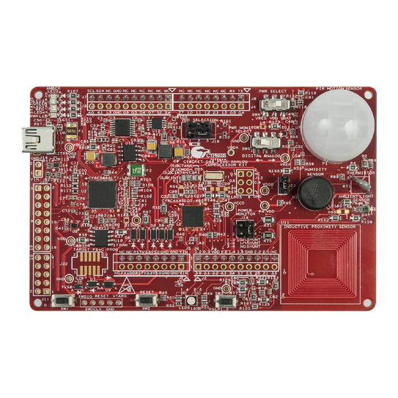
3.0 V when powered from the coin cell. The USB port is used as a power source and for programming and debugging your application on PSoC Analog Coprocessor device. Figure 1-2. CY8CKIT-048 PSoC Analog Coprocessor Pioneer Kit Top View PSoC Analog Coprocessor Pioneer Kit Guide, Doc. # 002-11190 Rev. **... - Page 10 Copyrights Figure 1-3. PSoC Analog Coprocessor Pioneer Kit Bottom View PSoC Analog Coprocessor Pioneer Kit Guide, Doc. # 002-11190 Rev. **...
- Page 11 Copyrights Figure 1-4. PSoC Analog Coprocessor Pioneer Board Pinout Description PSoC Analog Coprocessor Pioneer Kit Guide, Doc. # 002-11190 Rev. **...
-
Page 12: Psoc Creator
Figure 1-5. PSoC Creator Features PSoC Creator also enables you to tap into an entire tool ecosystem with integrated compiler chains and production programmers for PSoC devices. For more information, visit www.cypress.com/psoccreator. PSoC Analog Coprocessor Pioneer Kit Guide, Doc. # 002-11190 Rev. **... -
Page 13: Psoc Creator Code Examples
Copyrights 1.3.1 PSoC Creator Code Examples PSoC Creator includes a large number of code example. These examples are accessible from the PSoC Creator Start page, as shown in Figure 1-6. Code example can speed up your design process by starting you off with a complete design, instead of a blank page. -
Page 14: Kit Code Examples
Copyrights Figure 1-7. Code Example Projects with Sample Code 1.3.2 Kit Code Examples You can access the installed kit example projects from the PSoC Creator Start Page. To access these examples, expand the Kits under the section Examples and Kits; then, expand the specific kit to see the code examples. -
Page 15: Getting Started
Copyrights Getting Started This guide will help you be acquainted with the CY8CKIT-048 PSoC Analog Coprocessor Pioneer Kit: Software Installation chapter on page 19 describes the installation of the kit software. This ■ includes the PSoC Creator IDE to develop and debug the applications, and PSoC Programmer to program the .hex files on to the device. -
Page 16: Technical Support
Copyrights Technical Support For assistance, visit Cypress Support or contact customer support at +1(800) 541-4736 Ext. 2 (in the USA) or +1 (408) 943-2600 Ext. 2 (International). You can also use the following support resources if you need quick assistance: Self-help (Technical Documents) ■... - Page 17 Copyrights Table 1-2. Acronyms Used in this Document Acronym Definition Serial Peripheral Interface Serial Wire Debug UART Universal Asynchronous Receiver Transmitter Universal Serial Bus Watch Crystal Oscillator PSoC Analog Coprocessor Pioneer Kit Guide, Doc. # 002-11190 Rev. **...
-
Page 18: Software Installation
Before You Begin To install Cypress software, you will require administrator privileges. However, they are not required to run software that is already installed. Before you install the kit software, close any other Cypress software that is currently running. Install Software Follow these steps to install the PSoC Analog Coprocessor Pioneer Kit software: 1. - Page 19 PSoC Programmer 3.24.2 or later: This is installed as part of PSoC Creator installation or is available separately from www.cypress.com/programmer. 6. Choose the Typical, Custom, or Complete installation type (select Typical if you do not know which one to select) in the Product Installation Overview window, as shown in Figure 2-2.
-
Page 20: Uninstall Software
Uninstall Software The software can be uninstalled using one of the following methods: Go to Start > All Programs > Cypress > Cypress Update Manager and select the Uninstall ■ button that corresponds to the kit software. -
Page 21: Kit Operation
Kit Operation This chapter introduces you to the various features of the PSoC Analog Coprocessor Pioneer Kit. It primarily includes the kit block overview, onboard sensors, Analog Coprocessor functionality, programming and debugging functionality, KitProg2 USB-UART, and USB-I2C bridges. Theory of Operation The PSoC Analog Coprocessor Pioneer Kit is built around the PSoC Analog Coprocessor device. - Page 22 Copyrights Figure 3-2 shows the block diagram for the PSoC Analog Coprocessor Pioneer Kit. Figure 3-2. Block Diagram of PSoC Analog Coprocessor Pioneer Kit PSoC Analog Coprocessor Pioneer Kit Guide, Doc. # 002-11190 Rev. **...
-
Page 23: Onboard Sensors
Copyrights 3.1.1 Onboard Sensors The PSoC Analog Coprocessor Pioneer Kit has the following five onboard sensors: PIR motion sensor ■ Ambient light sensor ■ Thermistor ■ ■ Inductive proximity sensor Humidity sensor ■ 3.1.1.1 PIR Motion Sensor Figure 3-3 shows the circuit diagram of the PIR motion sensing. Figure 3-3. - Page 24 Copyrights First stage amplifier This block consists of an opamp that is internal to PSoC, external gain setting resistors (R118 and R119), and a filter capacitor (C81), as shown in Figure 3-3. The gain provided by the first stage amplifier is 681. Second stage amplifier This is an optional second stage amplifier implemented using a programmable gain amplifier (PGA) component of the PSoC Analog Coprocessor.
- Page 25 PSoC Analog Copro- cessor Pioneer Kit. The coil on the CY8CKIT-048 kit is used for inductive proximity sensing. The inductance of the coil changes when a metal object is placed in close proximity to the coil. The band pass filter network...
- Page 26 Kit. Figure 3-7. Humidity Sensing Circuit Diagram The capacitive type of humidity sensor is used on CY8CKIT-048. The output capacitance of humidity sensor H1 varies based on the humidity value. The reference capacitor C90 is used for calibration purposes.
-
Page 27: Analog Coprocessor
I2C/UART. 3.1.3 Use CY8CKIT-048 as General-Purpose Kit Some of the I/Os of the PSoC Analog Coprocessor device on the CY8CKIT-048 kit are connected to both the sensors as well as the headers through the 0- resistors as shown in Figure 3-9. - Page 28 Copyrights Figure 3-10. Example Sensor Connection The pin is connected to the sensor and the header by default. If a desired pin needs to be used from the header for some other purpose than the onboard sensor, then the pin needs to be disconnected from the sensor by removing the 0-...
- Page 29 Copyrights Table 3-1 shows the list of 0- resistors used to connect P2.0, P2.1, and P2.2 to the PIR motion sen- sor and to the header. Table 3-1. PIR Motion Sensor Pin Connection To Sensor To Header P2.0 R143 P2.1 R131 R132 P2.2...
-
Page 30: Programming And Debugging Psoc Analog Coprocessor Device
KitProg2. The KitProg2 is a multi-functional system, which includes a programmer, debugger, USB- I2C bridge, and a USB-UART bridge. A Cypress PSoC 5LP device is used to implement the KitProg2 functionality. The KitProg2 is integrated in most PSoC development kits. For more details on the KitProg2 functionality, refer to the KitProg2 User Guide in the kit installation directory: <Install_Directory>\CY8CKIT-048 PSoC Analog Coprocessor Pioneer Kit\<ver-... -
Page 31: Debugging Using Psoc Creator
Copyrights Figure 3-12. Connect USB Cable to USB Connector on the Kit 2. Open the desired project in PSoC Creator. For this, go to File > Open > Project/Workspace. This provides the option to browse to and open your saved project. 3. -
Page 32: Usb-I2C Bridge
Copyrights USB-I2C Bridge The KitProg2 can function as a USB-I2C bridge and communicate with the Bridge Control Panel (BCP) software utility. The I2C lines on the PSoC Analog Coprocessor device are P4[1] (SDA) and P4[0] (SCL), which are hardwired on the board to the I2C lines of the KitProg2. The USB-I2C supports I2C speeds of 50 kHz, 100 kHz, 400 kHz, and 1 MHz. -
Page 33: Code Examples
1. Launch PSoC Creator from Start > All Programs > Cypress > PSoC Creator <version> > PSoC Creator <version>. 2. On the Start page, click CY8CKIT-048 under Examples and Kits > Kits. A list of code examples appears, as shown in Figure 4-1. - Page 34 Copyrights 4. Build the code example by choosing Build > Build <Project Name>. A .hex file is generated after the build process. 5. Connect the PSoC Analog Coprocessor Pioneer Kit to the PC using the USB cable connected to connector J13 as shown in Figure 3-12, to program the kit with this code example.
- Page 35 Copyrights Figure 4-3. Connect Device from PSoC Creator and Program 9. After programming is successful, the green LED (LED3) and amber LED (LED2) on the board will turn on. PSoC Analog Coprocessor Pioneer Kit Guide, Doc. # 002-11190 Rev. **...
-
Page 36: Code Examples
Copyrights Code Examples Table shows a list of code examples that can be used with this kit. Table 4-1. Code Examples Project Title/Description This code example demonstrates how to interface the PSoC Analog Coprocessor with a PIR motion sensor. This code CE211301 PIR Motion Sensing example measures the voltage signal from the PIR sensor to detect the movement of an IR emitting body. -
Page 37: Appendix
Appendix Schematics Refer to the schematics file in the following path: <Install_Directory>\CY8CKIT-048 PSoC Analog Coprocessor Pioneer Kit\1.0\ Hardware\CY8CKIT-048 Schematic.pdf Hardware Functional Description This section provides a detailed explanation on the individual hardware blocks of the PSoC Analog Coprocessor Pioneer Kit. - Page 38 Copyrights A.2.3 Power Supply System The power supply system is designed to support 1.8-V, 3.3-V, or 5-V operation when supplied from the external VIN, and 1.8-V or 3.3-V operation when supplied from the Mini-B USB connector. The selection between 1.8 V, 3.3 V, and 5 V is made through a 4-pin jumper. If the board is powered from the Mini-B USB connector, it provides 3.3 V and 5 V to the Arduino-compatible power headers and I/O headers.
- Page 39 Copyrights Figure A-2. Detailed Circuit of Power Supply System Table A-1 lists the jumper (J18) settings for different voltages. Table A-1. Jumper (J18) Settings for Different Voltage Selection Jumper (J18) Setting O/P Voltage Mode Short 4 and 2 1.8 V–5.0 V Programmable Short 3 and 2 5.0 V...
- Page 40 Copyrights A.2.5 Current Measurement Switch The kit has an onboard facility to monitor both analog and digital power consumed by the PSoC Ana- log Coprocessor. A 4-pin jumper (J16) and a DPDT switch (SW5) are provided for current measure- ment of digital and analog supplies to the PSoC Analog Coprocessor. The jumper (J16) is connected between the power supplies (digital/analog) of the PSoC Analog Coprocessor device and the power supply of the baseboard, and also across two shunt resistors of 10 ...
- Page 41 Copyrights A.2.6 Expansion Connectors A.2.6.1 Arduino Compatible Headers (J1, J2, J3, J4, and J12) This kit has five Arduino compatible headers—J1, J2, J3, J4, and J12. You can develop applications based on the Arduino shield’s hardware. The J1 header contains I/O pins for reset, I/O reference voltage (IOREF), and power supply lines.
- Page 42 Copyrights A.2.11 Cypress Ferroelectric RAM (F-RAM) The PSoC Analog Coprocessor Pioneer Kit contains an F-RAM device (FM24V10-G) that can be accessed through I2C lines P4 [0] and P4 [1] of the PSoC Analog Coprocessor device. The F-RAM has a capacity of 1-Mbit (128 KB) with an I2C speed up to 1 Mbps. The I2C slave address of the F- RAM device is 7 bits wide, and the two least significant bits are configurable through physical pins.
-
Page 43: Using The Fm24V10 F-Ram
Note: The 8-pin SOIC footprint provided for the F-RAM FM24V10 on the PSoC Analog Processor Pioneer Kit is compatible with all I2C-based F-RAM devices from Cypress (FM24Vxx, FM24CLxx, and CY15BxxxJ parts). The F-RAM parts with more than 64 KB size support only four addresses (four devices of the same type on the same I2C bus);... - Page 44 Copyrights A.3.2 High Speed Mode (Hs-mode) The FM24V10 supports a 3.4-MHz high-speed mode. A master code (00001XXXb) must be issued to place the device into high-speed mode. Communication between master and slave will then be enabled for speeds up to 3.4 MHz. A STOP condition will exit Hs-mode. Single- and multiple-byte reads and writes are supported.
- Page 45 Copyrights Figure A-8. F-RAM Single-Byte and Multiple-Byte Read Packet Structure As the figures show, operations start with the slave address followed by the memory address. For write operations, the bus master sends the slave address and memory address followed by one or more data bytes.
- Page 46 Copyrights Migrating Projects Across Different Pioneer Series Kits The Cypress Pioneer series kits are Arduino Uno-compatible and have some common onboard peripherals such as RGB LED, CapSense and User Switch. However, the pin mapping in each of the boards is different due to differences in pin functions of the PSoC device used. This section lists the pin mapping of the Pioneer series kits to allow for easy migration of projects across different kits.
- Page 47 Copyrights A.4.1 Arduino Uno Compatible Headers Table A-3. J1 Arduino Compatible Header Pin Map Pioneer Series Kits Arduino CY8CKIT- CY8CKIT- CY8CKIT-042- CY8CKIT- CY8CKIT- CY8CKIT- CY8CKIT- V5.0 V5.0 V5.0 V5.0 V5.0 V5.0 V5.0 3.3V V3.3 V3.3 V3.3 V3.3 V3.3 V3.3 V3.3 RESET RESET RESET...
- Page 48 P0[7] P0[7] P0[7] Bill of Materials Refer to the BOM file in the following path in the kit software installed: <Install_Directory>\CY8CKIT-048 PSoC Analog Coprocessor Pioneer Kit\1.0 \Hardware\CY8CKIT-048 PCBA BOM.xlsx PSoC Analog Coprocessor Pioneer Kit Guide, Doc. # 002-11190 Rev. **...
- Page 49 Revision History CY8CKIT-048 PSoC® Analog Coprocessor Pioneer Kit Guide Revision History Document Title: CY8CKIT-048 PSoC® Analog Coprocessor Pioneer Kit Guide Document Number: 002-11190 Origin of Revision Issue Date Description of Change Change 02/25/2016 DIMA Initial version of the kit guide.
Need help?
Do you have a question about the CY8CKIT-048 and is the answer not in the manual?
Questions and answers