
Subscribe to Our Youtube Channel
Related Manuals for Cypress CY8CKIT-017


Summary of Contents for Cypress CY8CKIT-017
- Page 1 CY8CKIT-017 CAN/LIN Expansion Board Kit Guide Doc. # 001-57814 Rev. *D Cypress Semiconductor 198 Champion Court San Jose, CA 95134-1709 Phone (USA): 800.858.1810 Phone (Intnl): 408.943.2600 http://www.cypress.com...
- Page 2 Cypress Source Code and derivative works for the sole purpose of creating custom soft- ware and or firmware in support of licensee product to be used only in conjunction with a Cypress integrated circuit as speci- fied in the applicable agreement.
-
Page 3: Table Of Contents
4.2.1 CAN Bus Clock Accuracy................24 4.2.2 CAN Bus Connector..................24 4.2.3 CAN Bus Termination..................25 4.2.4 Choke Footprint....................25 4.2.5 CAN Circuit Isolation ..................25 LIN Physical Layer Transceiver Circuits ..............26 4.3.1 LIN Bus Connectors ..................26 CY8CKIT-017 CAN/LIN Expansion Board Kit Guide, Doc. # 001-57814 Rev. *D... - Page 4 5.3.5.3 Timer ....................56 5.3.5.4 ISR Component ................57 5.3.5.5 Design Wide Resources ..............57 A. Appendix Schematic........................61 Bill of Materials (BOM)....................62 Regulatory Compliance Information ................62 CY8CKIT-017 CAN/LIN Expansion Board Kit Guide, Doc. # 001-57814 Rev. *D...
-
Page 5: Safety Information
If such interference is detected, suitable mitigating measures should be taken. The CY8CKIT-017 as shipped from the factory has been verified to meet with requirements of CE as a Class A product. - Page 6 Handling Boards CY8CKIT-017 boards are sensitive to ESD. Hold the board only by its edges. After removing the board from its box, place it on a grounded, static free surface. Use a conductive foam pad if available.
-
Page 7: Introduction
Cypress Technical Support. Kit Compatibility This kit contains an expansion board and requires other Cypress kits to use it. It is designed to add CAN and LIN capabilities to the CY8CKIT-001 PSoC Development Kit (DVK). This DVK supports PSoC 1, PSoC 3, and PSoC 5 families. However, it may be necessary to obtain or purchase additional processor modules for the CY8CKIT-001 to develop applications for a particular PSoC device family. -
Page 8: Psoc Creator
Introduction For detailed information about the differences between PSoC 1, PSoC 3, and PSoC 5 devices, go to http://www.cypress.com/psoc. For more information about Cypress' kits, go to the Cypress Store at http://www.cypress.com/shop. PSoC Creator Cypress' PSoC Creator software is a state-of-the-art, easy-to-use software Integrated Development Environment (IDE). -
Page 9: Technical Support
Introduction Technical Support If you have any technical questions or issues related to this kit, call Cypress Customer Support +1 (800) 541-4736 Ext. 8 (in the USA), +1 (408) 943-2600 Ext. 8 (International), or visit http://www.cypress.com/go/support Document History Revision Release Date... - Page 10 Introduction CY8CKIT-017 CAN/LIN Expansion Board Kit Guide, Doc. # 001-57814 Rev. *D...
-
Page 11: Installation
2.2.2 Installation from Internet Follow these steps to install the CY8CKIT-017 CAN/LIN EBK software from the internet (this is done to ensure that the latest software is installed): 1. Insert the kit CD into your computer. -
Page 12: Software Uninstallation
Software Uninstallation Follow these steps to uninstall the CY8CKIT-017 CAN/LIN EBK software: 1. Open the Cypress Update Manager program. This is a program that is installed along with other Cypress software. 2. Click the Uninstall button associated with the CY8CKIT-017 kit software. -
Page 13: Kit Operation
Programming PSoC 3 Device The code examples are provided on the Start Page of PSoC Creator after the CY8CKIT-017 kit contents are installed. This section provides details on programming the PSoC 3 device. To program the ‘CAN_Example_1’ project to the PSoC 3 silicon, follow these steps: 1. - Page 14 Note See the PSoC Development Kit Board Guide for details on connecting and programming PSoC devices. 4. Click on the code example, CAN_Example_1 located in Examples and Kits on the Start Page of PSoC Creator. Figure 3-2. PSoC Creator Start Page CY8CKIT-017 CAN/LIN Expansion Board Kit Guide, Doc. # 001-57814 Rev. *D...
- Page 15 9. Reset the device by pressing the SW4 switch on the DVK; see Figure 3-5. Figure 3-5. Reset 10.Follow steps 1 through 9 to program other code examples, CAN_Example_2 and LIN_Example, on PSoC 3. CY8CKIT-017 CAN/LIN Expansion Board Kit Guide, Doc. # 001-57814 Rev. *D...
-
Page 16: Hardware Connections
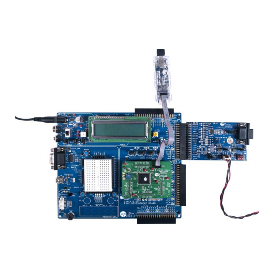
CAN Communication Hardware Setup 1. Connect the CAN/LIN expansion board to port A of CY8CKIT-001 DVK, as shown in Figure 3-1. 2. Connect a second CY8CKIT-017 expansion board to port A of a second CY8CKIT-001 DVK, as shown in Figure 3-1. - Page 17 7. Power up one DVK board with the 12-V power supply. Then, power up the other DVK with a 12-V power supply. The second DVK must be powered up within approximately 5 seconds of powering the first DVK. CY8CKIT-017 CAN/LIN Expansion Board Kit Guide, Doc. # 001-57814 Rev. *D...
-
Page 18: Lin Communication Hardware Setup
3. Connect Vbat, LIN bus, and GND of the LIN analyzer/LIN master to S_LIN (P5) connector of EBK. See LIN Bus Connectors on page 26 for details of LIN bus connectors. CY8CKIT-017 CAN/LIN Expansion Board Kit Guide, Doc. # 001-57814 Rev. *D... - Page 19 4. Connect a 12-V power supply adapter, which is supplied along with the CY8CKIT-001 DVK to the power jack of the DVK. Note If you are using the CY8CKIT-030 PSoC 3 DVK, connect the CY8CKIT-017 EBK to port E. CY8CKIT-017 CAN/LIN Expansion Board Kit Guide, Doc. # 001-57814 Rev. *D...
-
Page 20: Verify Functionality
1. When the LIN_Example project starts, the LIN Slave component is initialized. If the startup is suc- cessful, the ‘LINS Initialize Successful’ message is displayed on the LCD, followed by ‘Send the 8 bytes of data with ID 0x10’. CY8CKIT-017 CAN/LIN Expansion Board Kit Guide, Doc. # 001-57814 Rev. *D... - Page 21 5. When the frame with ID 0x11 is received, the data is sent to the LIN master. The frame ID and values of sent data is displayed on the LCD for 12 seconds. CY8CKIT-017 CAN/LIN Expansion Board Kit Guide, Doc. # 001-57814 Rev. *D...
-
Page 22: Using A Can Bus Analyzer Tool
Data published by LIN Slave Using a CAN Bus Analyzer Tool This kit functions most effectively when two CY8CKIT-001 DVKs and two CY8CKIT-017 EBKs are available. However, it is also possible to replace one CY8CKIT-001 DVK and one CY8CKIT-017 EBK with a CAN bus analyzer or emulator tool. It is even possible to use any other CAN node to communicate with this kit. -
Page 23: Hardware
The LEDs functional block consists of three, active-low LEDs that can provide indications. These LEDs are driven by PSoC pins. The 40-pin (2x20) connector connects the configured PSoC I/O pins to the various circuits on the expansion board. CY8CKIT-017 CAN/LIN Expansion Board Kit Guide, Doc. # 001-57814 Rev. *D... -
Page 24: Can Physical Layer Transceiver Circuit
By default, pin 9 of the CAN connector is left floating. However, if the CANEXTPWR jumper (JP3) is populated, pin 9 of the CAN connector is connected to the VIN power rail of the DVK and EBK. This CY8CKIT-017 CAN/LIN Expansion Board Kit Guide, Doc. # 001-57814 Rev. *D... -
Page 25: Can Bus Termination
CAN circuit does not interfere with any other circuits that share the same pins. The footprints for R3, R5, and R10 are designed so that they can be reconnected easily with a ‘solder jumper’ instead of repopulating the footprints with a 0- resistor. CY8CKIT-017 CAN/LIN Expansion Board Kit Guide, Doc. # 001-57814 Rev. *D... -
Page 26: Lin Physical Layer Transceiver Circuits
Both LIN circuits can be completely isolated from the rest of the CY8CKIT-001 DVK by removing resistors R19, R23, and R25 (to isolate the LIN1 circuit) or R20, R24, and R26 (to isolate the LIN2 CY8CKIT-017 CAN/LIN Expansion Board Kit Guide, Doc. # 001-57814 Rev. *D... -
Page 27: Using The Lin Transceiver Nwake Pins
R2, which is a 0- resistor. This is useful if the LEDs are not needed, but other circuits on the EBK are. In this case, isolating the LEDs ensures that they do not interfere with other circuits that share the same pins. CY8CKIT-017 CAN/LIN Expansion Board Kit Guide, Doc. # 001-57814 Rev. *D... -
Page 28: Port Options With Cy8Ckit-001 Dvk
P0_4 P7_4 P4_3 P0_3 P7_3 P4_2 P0_2 P7_2 P4_1 P0_1 P7_1 P4_0 P0_0 P7_0 RESRV 9 RESRV 1 RESRV 12 P12_3 P12_3 P12_3 P12_2 P12_2 P12_2 P12_1 P12_1 P12_1 CY8CKIT-017 CAN/LIN Expansion Board Kit Guide, Doc. # 001-57814 Rev. *D... -
Page 29: Jumper Settings Of Cy8Ckit-001 Dvk For Using Port B
4.5.2 Debugging Restrictions When Using Port B When the CY8CKIT-017 EBK occupies port B, debugging is possible only through Serial Wire Debug (SWD) interface. It is not possible through JTAG and Serial Wire Viewer (SWV) debug interfaces because expansion board circuits conflict with GPIO pins of these (JTAG and SWV) interfaces. -
Page 30: Default Switch And Jumper Settings
Hardware 001 boards (both with CY8CKIT-017 EBKs) that are connected to each other between their CAN connectors or LIN connectors. In this case, it is useful to allow the VIN power supply of one DVK to power up the other DVK (and its EBK) through the LIN or CAN header. -
Page 31: Code Examples
Code Examples The CAN_Example_1 project demonstrates the implementation of a CAN node using a CY8CKIT- 001 DVK, a CY8CKIT-009 PSoC 3 processor module, and a CY8CKIT-017 CAN/LIN EBK. The test setup shown in Figure 3-8 on page 17 consists of two CAN nodes, created using two CY8CKIT-001 DVKs, two CY8CKIT-009 PSoC 3 processor modules, and two CY8CKIT-017 CAN/LIN EBKs con- nected by a DB9 cable. - Page 32 TxError == 0 && Turn Off Amber RxError == 0 and Red TxError > 127 or Turn On Red, RxError > 127 Turn Off Amber Turn On Amber, Turn Off Red CY8CKIT-017 CAN/LIN Expansion Board Kit Guide, Doc. # 001-57814 Rev. *D...
-
Page 33: Running The Code Example
PSoC Creator Project Details PSoC Creator offers a flexible hardware and software co-design environment to create and configure the programmable peripherals. Figure 5-3. PSoC Creator Top Level Design For CAN_Example_1 Project CY8CKIT-017 CAN/LIN Expansion Board Kit Guide, Doc. # 001-57814 Rev. *D... -
Page 34: Can
Any tabs not shown have default settings. This is valid for all components of all code examples. Figure 5-4. CAN Configuration: General Tab Figure 5-5. CAN Configuration: Timing Tab CY8CKIT-017 CAN/LIN Expansion Board Kit Guide, Doc. # 001-57814 Rev. *D... - Page 35 Code Examples Figure 5-6. CAN Configuration: Interrupt Tab Figure 5-7. CAN Configuration: Receive Buffers Tab CY8CKIT-017 CAN/LIN Expansion Board Kit Guide, Doc. # 001-57814 Rev. *D...
-
Page 36: Adc
Code Examples Figure 5-8. CAN Configuration: Transmit Buffers Tab 5.1.4.2 The ADC component is used to sample the potentiometer input. Figure 5-9. ADC Configuration: Configure Tab CY8CKIT-017 CAN/LIN Expansion Board Kit Guide, Doc. # 001-57814 Rev. *D... - Page 37 Code Examples Figure 5-10. ADC Configuration: Common Tab CY8CKIT-017 CAN/LIN Expansion Board Kit Guide, Doc. # 001-57814 Rev. *D...
-
Page 38: Pot_In
The POT_IN pin is used to input the analog signal from the potentiometer. The pin’s drive mode is configured as High Impedance Analog, which is the default value. Figure 5-11. POT_IN Configuration: Pins > Type Tab Figure 5-12. POT_IN Configuration: Pins > General Tab CY8CKIT-017 CAN/LIN Expansion Board Kit Guide, Doc. # 001-57814 Rev. *D... -
Page 39: Status_Reg
BUS_CLK The BUS_CLK is used as the latching clock for the STATUS_REG component. This is an existing, high-frequency clock in the chip. Figure 5-14. BUS_CLK Configuration: Configure Clock Tab CY8CKIT-017 CAN/LIN Expansion Board Kit Guide, Doc. # 001-57814 Rev. *D... -
Page 40: Loopclk
LOOPCLK is configured to generate a 100 Hz clock, which is used to generate a 10 ms period in the firmware. Figure 5-15. LOOPCLK Configuration: Configure Clock Tab Figure 5-16. LOOPCLK Configuration: Advanced Tab CY8CKIT-017 CAN/LIN Expansion Board Kit Guide, Doc. # 001-57814 Rev. *D... -
Page 41: Lcd
CAN_TX is the CAN bus transmit signal pin. This pin is configured as an output pin with a strong drive mode. It must be connected to the CAN TX input of the external CAN transceiver. Figure 5-18. CAN_TX Configuration: Pins > Type Tab CY8CKIT-017 CAN/LIN Expansion Board Kit Guide, Doc. # 001-57814 Rev. *D... -
Page 42: Can_Rx
CAN_RX is the CAN bus receive signal pin. This pin is configured as an input pin with a high imped- ance drive mode. It must be connected to the CAN RX pin of the external CAN transceiver. Figure 5-20. CAN_RX Configuration: Pin > Type Tab CY8CKIT-017 CAN/LIN Expansion Board Kit Guide, Doc. # 001-57814 Rev. *D... - Page 43 Code Examples Figure 5-21. CAN_RX Configuration: Pins > General Tab Figure 5-22. CAN_RX Configuration: Pins > Input Tab CY8CKIT-017 CAN/LIN Expansion Board Kit Guide, Doc. # 001-57814 Rev. *D...
-
Page 44: Can_En
CAN_EN is external CAN transceiver enable signal pin. This pin is configured as an output pin with strong drive mode. Figure 5-23. CAN_EN Configuration: Pins > Type Tab Figure 5-24. CAN_EN Configuration: Pins > General Tab CY8CKIT-017 CAN/LIN Expansion Board Kit Guide, Doc. # 001-57814 Rev. *D... -
Page 45: Can_Led_Ok
CAN_LED_OK CAN_LED_OK is configured as a software controlled output pin with strong drive mode and initial state as high. This pin is connected to the green LED on the CY8CKIT-017 CAN/LIN EBK. Figure 5-25. CAN_LED_OK Configuration: Pins > Type Tab Figure 5-26. -
Page 46: Can_Led_Warn
CAN_LED_WARN CAN_LED_WARN is configured as a software controlled output pin with strong drive mode and initial state as high. This pin is connected to the amber LED on the CY8CKIT-017 CAN/LIN EBK. Figure 5-27. CAN_LED_WARN Configuration: Pins > Type Tab Figure 5-28. -
Page 47: Can_Led_Err
CAN_LED_ERR CAN_LED_ERR is configured as a software controlled output pin with strong drive mode and initial state as high. This pin is connected to the red LED on the CY8CKIT-017 CAN/LIN EBK. Figure 5-29. CAN_LED_ERR Configuration: Pins > Type Tab Figure 5-30. -
Page 48: Design Wide Resources
CAN Bus Clock Accuracy on page 24 for more information on clock source requirements for the PSoC CAN controller. All clock settings of this code example are shown in Figure 5-32 Figure 5-33 on page CY8CKIT-017 CAN/LIN Expansion Board Kit Guide, Doc. # 001-57814 Rev. *D... - Page 49 Code Examples Figure 5-32. Clock Setting Figure 5-33. System Clock Configuration CY8CKIT-017 CAN/LIN Expansion Board Kit Guide, Doc. # 001-57814 Rev. *D...
-
Page 50: Code Example 2: Can_Example_2
6 seconds and interrupt is generated on the Terminal Count (TC). This will be used to change the user interface messages on LCD display. CY8CKIT-017 CAN/LIN Expansion Board Kit Guide, Doc. # 001-57814 Rev. *D... -
Page 51: Firmware Flowcharts
(data present in signals InSig1 and present in signals Out Sig1 and InArraySig)” on LCD OutArraySig)” on LCD Write Data of Signal InArraySig to OutArraySig CY8CKIT-017 CAN/LIN Expansion Board Kit Guide, Doc. # 001-57814 Rev. *D... -
Page 52: Running The Code Example
For more information on hardware connections, see Hardware Connections on page 5.3.4 Verifying Output See the verify functionality described in section LIN Communication on page 20 for the LIN code example verification. CY8CKIT-017 CAN/LIN Expansion Board Kit Guide, Doc. # 001-57814 Rev. *D... -
Page 53: Psoc Creator Project Details
The component figure shows only tabs in which settings have been changed from default states ■ or in which critical settings exist for proper operation. Any tabs not shown have default settings. This is valid for all components of all code examples. CY8CKIT-017 CAN/LIN Expansion Board Kit Guide, Doc. # 001-57814 Rev. *D... - Page 54 Code Examples Figure 5-37. LIN Configuration: General Tab Figure 5-38. LIN Configuration: Baud Rate Tab CY8CKIT-017 CAN/LIN Expansion Board Kit Guide, Doc. # 001-57814 Rev. *D...
- Page 55 Code Examples Figure 5-39. LIN Configuration: Frames Tab Figure 5-40. LIN Configuration: Signals Tab CY8CKIT-017 CAN/LIN Expansion Board Kit Guide, Doc. # 001-57814 Rev. *D...
-
Page 56: Character Lcd
IDs. Figure 5-41. Character LCD Configuration: General Tab 5.3.5.3 Timer Timer uses UDB based implementation and period is configured to 6 seconds. Figure 5-42. Timer Configuration: Configure Tab CY8CKIT-017 CAN/LIN Expansion Board Kit Guide, Doc. # 001-57814 Rev. *D... -
Page 57: Isr Component
Creator (in the .cydwr file) to match port B or port C according to Table 4-4 on page 28. The pin assignment for this code example is shown in Figure 5-44. CY8CKIT-017 CAN/LIN Expansion Board Kit Guide, Doc. # 001-57814 Rev. *D... - Page 58 Table 5-2. Pin Assignments details of LIN Example Project Signal CY8CKIT-001 DVK (Port A) CY8CKIT-030 DVK (Port E) P2[6:0] P2[6:0] L_RXD P5[1] P0[1] L_TXD P5[5] P0[5] NSLP P5[3] P0[3] CY8CKIT-017 CAN/LIN Expansion Board Kit Guide, Doc. # 001-57814 Rev. *D...
- Page 59 Code Examples Figure 5-45. Clock Settings Figure 5-46. System Clock Configuration CY8CKIT-017 CAN/LIN Expansion Board Kit Guide, Doc. # 001-57814 Rev. *D...
- Page 60 Code Examples CY8CKIT-017 CAN/LIN Expansion Board Kit Guide, Doc. # 001-57814 Rev. *D...
-
Page 61: Appendix
Appendix Schematic CY8CKIT-017 CAN/LIN Expansion Board Kit Guide, Doc. # 001-57814 Rev. *D... -
Page 62: Bill Of Materials (Bom)
TP19(GND..) Keystone Electronics 5002 (0.040" (1.016mm) Hole Diameter) Regulatory Compliance Information CY8CKIT-017 has been tested and verified to comply with the following electromagnetic compatibil- ity (EMC) regulations. CISPR 22 - Emissions ■ EN 55022 Class A - Immunity (Europe) ■...
Need help?
Do you have a question about the CY8CKIT-017 and is the answer not in the manual?
Questions and answers