Table of Contents
Advertisement
Quick Links
Advertisement
Table of Contents

Related Manuals for Cypress CY8CKIT-036


Summary of Contents for Cypress CY8CKIT-036
- Page 1 CY8CKIT-036 ® PSoC Thermal Management Expansion Board Kit Guide Doc. No. 001-89649 Rev. ** Cypress Semiconductor 198 Champion Court San Jose, CA 95134-1709 Phone (USA): +1.800.858.1810 Phone (Intnl): +1.408.943.2600 www.cypress.com Arrow.com. Downloaded from...
- Page 2 PARTICULAR PURPOSE. Cypress reserves the right to make changes without further notice to the materials described herein. Cypress does not assume any liability arising out of the application or use of any product or circuit described herein. Cypress does not authorize its products for use as critical components in life-support systems where a malfunction or failure may reasonably be expected to result in significant injury to the user.
-
Page 3: Table Of Contents
One-Wire Digital Temperature Sensor ....................14 2.3.4 Diode Analog Temperature Sensors ....................... 14 Communication Interface ............................. 14 CY8CKIT-036 EBK 2x20 Pin Header ........................15 CY8CKIT-036 EBK Headers and Jumpers ......................16 Kit Operation ................................17 System Block Diagram and Theory of System Operation ..................17 Four-Wire Fan Control ............................ - Page 4 Appendix ..................................21 A.1. Schematics ................................21 A.2. Board Layout ............................... 25 A.3. Bill of Materials ..............................27 Revision History ................................29 Document Revision History ............................29 ® PSoC Thermal Management Expansion Board Kit Guide, Doc. No. 001-89649 Rev. ** Arrow.com.
-
Page 5: Safety Information
Safety Information The CY8CKIT-036 PSoC Thermal Management Expansion Board Kit is intended for use as a development platform for hardware or software in a laboratory environment. The board is an open system design, which does not include a shielded enclosure. Due to this reason the board may cause interference to other electrical or electronic devices in close proximity. - Page 6 Handling Boards CY8CKIT-036 boards are sensitive to ESD. Hold the board only by its edges. After removing the board from its box, place it on a grounded, static free surface. Use a conductive foam pad if available. Do not slide board over any surface.
-
Page 7: Introduction
CY8CKIT-036 with various PSoC devices. Refer to the kit webpage www.cypress.com/go/CY8CKIT-036 for the latest information on using CY8CKIT-036 with various PSoC devices. The webpage will be updated as new PSoC devices and development kits that work with CY8CKIT-036 are released to the market. 1.2.1 Beginner Resources An overview of various PSoC devices is available at www.cypress.com/psoc/. -
Page 8: Hardware Requirements
1.2.2 Hardware Requirements CY8CKIT-036 is designed to connect with the expansion ports of the various PSoC development kits so you can use one EBK to evaluate the entire portfolio of PSoC devices. Table 1-1 lists the hardware requirements for using CY8CKIT-036 with various PSoC devices. -
Page 9: Software Requirements
Each component in the rich mixed-signal Cypress Component Catalog is configured with a component customizer and includes a full set of dynamically generated API libraries. After the PSoC system has been configured, firmware can be written, compiled, and debugged within PSoC Creator or exported to top IDEs from IAR, Keil, and Eclipse. -
Page 10: Application Notes And Projects
1.2.4 Application Notes and Projects Cypress offers many application notes that pertain to CY8CKIT-036. Application notes cover the topics of four-wire fan control and temperature sensing using PSoC devices; they also provide associated projects. The Kit Operation section of this guide lists related application notes. In a thermal management application, the PSoC chip senses the temperature and controls the fan;... -
Page 11: Kit Hardware
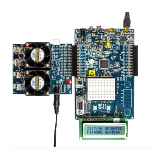
2.1 Kit Overview Figure 2-1 shows the CY8CKIT-036 EBK. The circuits associated with each sensor are boxed and labeled in the figure. The kit has two onboard four-wire fans, PWM temperature sensors, transistors connected in diode configuration, an I temperature sensor, and a one-wire temperature sensor. The kit also provides sockets for plugging in additional four-wire... -
Page 12: Four-Wire Fans
PWM control signal The fans require a 12-V power supply and usually take about 0.5 A of input current. The CY8CKIT-036 EBK includes a 12-V DC high-current power supply that is capable of providing the inrush current needed by the fans installed on the kit. -
Page 13: Temperature Sensors
CONV/IN input of the subsequent sensor. The OUT signal of the second sensor carries the PWM signals from both sensors. Many sensors can be daisy-chained in this fashion, with the final OUT signal carrying the PWM temperature encoding from all sensors in the daisy chain. Jumper J2 on the CY8CKIT-036 EBK, as shown in Figure... -
Page 14: One-Wire Digital Temperature Sensor
2.3.3 One-Wire Digital Temperature Sensor The CY8CKIT-036 EBK has a Maxim DS18S20 one-wire, high-precision digital temperature sensor installed. The DS18S20 digital thermometer provides 9-bit resolution Celsius temperature measurements and has an alarm function with nonvolatile user-programmable upper and lower trigger points. The DS18S20 communicates over a proprietary one-wire bus that by definition requires only one data line (and ground) to communicate with a host microprocessor. -
Page 15: Cy8Ckit-036 Ebk 2X20 Pin Header
2.5 CY8CKIT-036 EBK 2x20 Pin Header The 40-pin interface (2x20 pin header) provides a mechanism to connect CY8CKIT-036 EBK to a Cypress development kit platform. Table 2-2 lists the pin assignments of the 2x20 connector. Table 2-2. 2x20 Connector Pin Assignments... -
Page 16: Cy8Ckit-036 Ebk Headers And Jumpers
2.6 CY8CKIT-036 EBK Headers and Jumpers The CY8CKIT-036 EBK provides numerous jumpers. Table 2-3 lists the default jumper settings for the board. Table 2-3. CY8CKIT-036 EBK Jumper Settings Headers and Factory Default Jumpers Description Configuration Five-pin header for connecting an external host or management processor via I2C/SMBus/PMBus. -
Page 17: Kit Operation
The Appendix contains a schematic of the CY8CKIT-036 EBK, along with circuits associated with the four-wire fans and the different onboard temperature sensors. This section describes the theory of operation for each of those hardware sub- blocks in the EBK. -
Page 18: Pwm Output Digital Temperature Sensor
These application notes provide example projects that demonstrate different usage modes of four-wire fan control. In addition, they include a thermal management example project that uses the temperature sensors on the CY8CKIT-036 EBK to control the speed of the fans associated with a thermal zone. -
Page 19: Diode Analog Temperature Sensors
The code examples in the application note use an external calibration resistor for measuring the current ratio accurately. The calibration resistor is not part of CY8CKIT-036 and needs to be connected externally on the PSoC DVK used. Refer to the respective PSoC application notes for the value of the calibration resistor and for connection details. -
Page 20: C Temperature Sensor
SMBus interfaces and is specified for a temperature range of −40° C to +125° C. The TMP175 features three address pins, allowing up to eight devices to be connected per bus. In the CY8CKIT-036 EBK, the three address pins (A2, A1, A0) are tied to ground, and the sensor address is 7’b1001000. -
Page 21: Appendix
A. Appendix A.1. Schematics Power Supply Power VDD12 Default : VDD12 VDD12_EXT VDD12_EXT VDD12 VDD12 <-> VDD12_EXT VDD12 SM340A VDD12_EXT VDD12_DVK DC-12V VDD12 SM340A VDD12_DVK 0.1u 12V/3A JMP-3 SM340A VDD12 SM340A Default : VDD5 VDD3P3 VDD5 VDD5 VDD3P3 VDDIO DGND AGND VDDIO <->... - Page 22 Four-Wire Fan Sockets VDDIO VDD12 VDDIO VDD12 F1_DGND F2_DGND F1_VDD12 F2_VDD12 F1_TACH F2_TACH F1_PWM F2_PWM F1_DGND F2_DGND 4.7K 4.7K F1_VDD12 F2_VDD12 TACH1 F1_TACH TACH2 F2_TACH PWM1 F1_PWM PWM2 F2_PWM 0.1u 0.1u 0.1u 1.25MM PITCH 1 0.1u 1.25MM PITCH 1 2.54MM PITCH 1 2.54MM PITCH 1 VDDIO VDD12...
- Page 23 One-Wire Temperature Sensor VDDIO VDDIO 4.7K 0.1u ONEWIRE DS18S20 Temperature Diodes TD-I TD-A MMBT3094 MMBT3094 TD-K C Temperature Sensor VDDIO VDDIO 2.2K 2.2K 0.1u I2C-TEMP_SDA I2C-TEMP_SCL ALERT TMP175 I2C Address 8'b01001000 ® PSoC Thermal Management Expansion Board Kit Guide, Doc. No. 001-89649 Rev. ** Arrow.com.
- Page 24 PWM Temperature Sensors VDDIO VDDIO PWM-IN CONV/IN 0.1u FUNC SINGLE PWM-OUT TMP05 PWM_TMP DUAL JMP-3 Default : PWM_TMP <-> DUAL CONV/IN 0.1u FUNC TMP05 ® PSoC Thermal Management Expansion Board Kit Guide, Doc. No. 001-89649 Rev. ** Arrow.com. Arrow.com. Arrow.com. Arrow.com.
-
Page 25: Board Layout
A.2. Board Layout Top Layer Bottom Layer ® PSoC Thermal Management Expansion Board Kit Guide, Doc. No. 001-89649 Rev. ** Arrow.com. Arrow.com. Arrow.com. Arrow.com. Arrow.com. Arrow.com. Arrow.com. Arrow.com. Arrow.com. Arrow.com. Arrow.com. Arrow.com. Arrow.com. Arrow.com. Arrow.com. Arrow.com. Arrow.com. Arrow.com. Arrow.com. Arrow.com. Arrow.com. - Page 26 Top Silkscreen ® PSoC Thermal Management Expansion Board Kit Guide, Doc. No. 001-89649 Rev. ** Arrow.com. Arrow.com. Arrow.com. Arrow.com. Arrow.com. Arrow.com. Arrow.com. Arrow.com. Arrow.com. Arrow.com. Arrow.com. Arrow.com. Arrow.com. Arrow.com. Arrow.com. Arrow.com. Arrow.com. Arrow.com. Arrow.com. Arrow.com. Arrow.com. Arrow.com. Arrow.com. Arrow.com. Arrow.com. Arrow.com.
-
Page 27: Bill Of Materials
A.3. Bill of Materials Item Description Designator Value Manufacturer Manufacturer Part# C2,C5,C7,C11, Ceramic capacitor, C12,C13,C14, 0.1uF, +/-10%, 25 V, C15,C16,C17, 0.1u Taiyo Yuden TMK105BJ104KV-F X5R (0402) C18,C19,C20, C21,C22 22uF, +/-10%, 25 V, MURATA GRM32ER61E226KE15L X5R (1210) 10uF, +/-10%, 25 V, C9,C10,C23 MURATA GRM31CR61E106KA12... - Page 28 Item Description Designator Value Manufacturer Manufacturer Part# Mini jumper 2.54 pitch CHERNG WEEI CMJ-135BB open type (13.5) M3 35 mm, nickel- plated, round head M3 nickel-plated hexagonal nut DC brushless axial flow fan, 40 x 40 mm, DB04028B12UP014 four-wire, 12 V ®...
-
Page 29: Revision History
4. Revision History Document Revision History ® Document Title: PSoC Thermal Management Expansion Board Kit Guide Document Number: 001-89649 Revision Issue Date Origin of Description of Change Change 12/2/2013 VVSK Initial version of the kit guide ® PSoC Thermal Management Expansion Board Kit Guide, Doc. No. 001-89649 Rev. ** Arrow.com.
Need help?
Do you have a question about the CY8CKIT-036 and is the answer not in the manual?
Questions and answers