Advertisement
Available languages
Available languages
Quick Links
AVVERTENZE
Prima di ogni accensione della macchina verifi care sempre che il braciere sia completamente libero
e pulito.
E' assolutamente vietato introdurre manualmente pellet all'interno del braciere.
All'interno della stufa si trovano 3 confezioni di sali disidratanti da rimuovere defi nitivamente prima
di accendere la stufa: 1 all'interno della camera di combustione, 2 all'esterno della stufa.
Per un ottimale funzionamento del prodotto, l'azienda invita l'utilizzatore a regolare l'affl usso del
pellet in base al tipo di combustibile utilizzato. Vedi sezione "Regolazione carico pellet" del libretto
istruzioni.
L'apparecchio deve funzionare alla potenza 4 o 5 per 2 o 3 giorni in modo tale che le parti meccaniche
abbiano la possibilità di assestarsi.
WARNING
Always check before lighting the stove that the burning pot is completely free and clean.
Do not insert pellet manually into the combustion pot.
3 packagings dehydrating salts will be found in the stove to be removed completely before starting
the heater: 1 inside the burning chamber, 2 on the outside.
For a correct functioning of this product, the manufacturer kindly asks the fi nal user to set the pellet
feeding according to the type of combustible. Please read the chapter "Pellet Feeding Adjustment"
in "Use and Maintenance Manual".
This stove must function at middle power (power 4 or 5) for 2 or 3 days in order to allow a better
settlement of the mechanical components.
ACHTUNG
Vor jeder Anzündung immer kontrollieren, dass die Brennschale frei und sauber ist.
Es ist verboten die Pellet in die Schale mit Händen zu werfen.
Im Pelletsofen sind 3 Packungen Trockensalz zu fi nden die anlässlich der Inbetriebnahme entfernt
werden müssen:1 in der Brennkamer und 2 sind ausserhalb des Ofens.
Zum dem optimalen Betrieb dieses Produktes bittet Der Hersteller den Benutzer darum, die
Pelletszufuhr gëmaβ dem verwendeten brennstoff einzustellen. Lesen Sie bitte den Paragraph
„Reglung der Pellets-Zufuhr" in der „Bedienungs- und Aufstellungsanleitung".
Das Gerät soll 2 oder 3 Tage auf Mittelleistung funktionieren (Stufe 4 oder 5) so dass die
mechanischeTeile sich einlaufen können.
ATTENTION
Avant d'allumer le poêle toujours contrôler que le brasier soit complètement libre et propre.
N'introduisez pas pellet manuellement dans le brasier.
A l'intérieur du poêle Vous retrouverez 3 paquets de sels déshydratants à enlever complètement ,
S.V.P., lors de la mise à feu : 1 dans le chambre de combustion, 2 à l'extérieur du poêle.
Pour un emploi optimal du produit, le producteur prie l'usager de bien vouloir régler le chargement
du pellet selon le type de combustible. Veuillez lire le paragraphe « Réglage charge Pellet » dans le
« Manuel d'instructions et entretien ».
L'appareil doit fonctionner à puissance 4 ou 5 pour 2 ou 3 jours, de façon que les parties mécaniques
puissent se tasser.
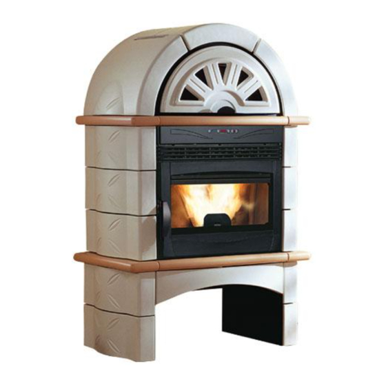
FALO' 1XLP
Advertisement

Related Manuals for Extraflame FALO 1XLP


Summary of Contents for Extraflame FALO 1XLP
- Page 1 AVVERTENZE Prima di ogni accensione della macchina verifi care sempre che il braciere sia completamente libero e pulito. E’ assolutamente vietato introdurre manualmente pellet all’interno del braciere. All’interno della stufa si trovano 3 confezioni di sali disidratanti da rimuovere defi nitivamente prima di accendere la stufa: 1 all’interno della camera di combustione, 2 all’esterno della stufa.
- Page 2 477.5 477.5 FALO’ 1XLP...
- Page 3 Stufa a pellet modello / pellet stove model : Falò 1XLP EN 14785 : 2006 Caratteristiche Features U.M. Peso Weight Altezza Height 1522 Larghezza Width Profondità Depth Diametro tubo scarico fumi Outlet fumes pipe diameter Diametro tubo aspirazione aria Air intake pipe diameter Volume di riscaldamento max.
- Page 4 Poêle à pellets modèle / Pelletofenmodell : Falò 1XLP EN 14785 : 2006 Données Eigenschaften U.M. Poids Gewicht Hauteur Höhe 1522 Largeur Breite Profondeur Tiefe Diamètre tuyau évacuation fumées Durchmesser Rauchabzugsrohr Diamètre tuyau aspiration air Durchmesser Luftansaugrohr Volume de réchauff ement max Max.
-
Page 5: Istruzioni Di Montaggio
ITALIANO ISTRUZIONI DI MONTAGGIO INSTALLAZIONE CONDOTTO EVACUAZIONE FUMI Per la serie FALO’ sono stati previsti 2 sistemi di evacuazione fumi che permettono di adattare il prodotto acquistato alle esigenze del cliente. I sistemi previsti sono i seguenti: evacuazione posteriore evacuazione superiore (con l’ausilio del kit supplementare) L’immagine sottostante mostra le 2 possibili installazioni. - Page 6 ITALIANO Fase 2 Partendo da un lato agganciare la piastrella (1) in basso negli appositi agganci del telaio di supporto. Ripetere la medesima operazione con la piastrella superiore (2). Seguendo il verso delle frecce di fi gura posizionare la piastrella anteriore (3). A questo punto sorreggerla e completare il lato opposto (4 e 5) come descritto per le piastrelle 1 e 2.
- Page 7 ITALIANO Fase 5 Agganciare la due piastrelle superiori mancanti (E e F ) ai relativi supporti metallici utilizzando le apposite aste di ancoraggio come in fi gura. Fase 6 A questo punto agganciare i 2 assiemi premontati utilizzando l’asta tolta in precedenza. Fase 7 Posizionare le 2 piastrelle laterali (G e H) fi ssandole leggermente con le viti e le rondelle ovalizzate premontate sul telaio (la...
- Page 8 ITALIANO Fase 8 Appoggiare le piastrelle (L e M) sulla cupola della stufa fi ssandole alle squadrette di ancoraggio con le viti in dotazione. Di seguito appoggiare le 2 piastrelle (N e O) e il coperchio verniciato nero nella parte superiore. Fase 9 Infi ne posizionare la maiolica anteriore (P) utilizzando le 3 piastrine nere e le 4 viti di fi ssaggio.
- Page 9 ENGLISH ASSEMBLY INSTRUCTIONS INSTALLATION SMOKE EXTRACTION FLUE For the series FALO’ , 2 systems of smoke extraction have been foreseen allowing adapting the purchased product to the customer’s needs. The foreseen systems are the following: Rear extraction Upper extraction (with the help of the additional kit) The fi gure here below shows the 2 possible ways of installation.
- Page 10 ENGLISH Step 2 Starting from one side, hook the tile (1) at the bottom in the proper hooks of the support frame. Repeat the same operation with the upper tile (2). Following the arrows shown in fi gure, place the front tile (3). At this point, support it and complete the opposite side (4 and 5) as described for tiles 1 and 2.
- Page 11 ENGLISH Step 5 Hook the two missing upper tiles (E and F) to the related metallic supports using the proper hooking rods as shown in fi gure. Step 6 Now, hook the 2 pre-assembled assemblies using the rod that has been removed before. Step 7 Place the 2 side tiles (G and H) tightening them slightly with the screws and the ovalized washers pre-assembled on the...
- Page 12 ENGLISH Step 8 Lean the tiles (L and M) on the dome of the stove tightening them to the hooking squares with the supplied screws. Then, lean the 2 tiles (N and O) and the black painted cover on the upper part.
- Page 13 FRANÇAIS INSTRUCTIONS PUOR LE MONTAGE INSTALLATION CONDUIT EVACUATION FUMEES Pour la série FALO’ on a prévu 2 systèmes d’évacuation fumées permettant d’adapter le produit acheté aux exigences du client. Les systèmes prévus sont les suivants: évacuation postérieure évacuation supérieure (à l’aide du kit additionnel) L’image en bas montre les 2 possibles installations.
- Page 14 FRANÇAIS Phase 2 Partant d’un côté, accrocher le carreau (1) en bas dans les crochets appropriées du châssis de support. Répéter la même opération avec le carreau supérieur (2). En suivant le vers des fl èches de fi gure, positionner le carreau antérieur(3). A’ ce point la soutenir et compléter le côté...
- Page 15 FRANÇAIS Phase 5 Accrocher les deux carreaux supérieurs qui manquent (E et F) aux relatifs supports métalliques utilisant les tiges appropriées d’ancrage comme dans la fi gure. Phase 6 A’ ce point accrocher les 2 groupes remontés utilisant la tige enlevée en précédence.
- Page 16 FRANÇAIS Phase 8 Appuyer les carreaux (L et M) sur la coupole de la poêle en les fi xant aux équerres d’ancrage avec les vis en dotation. Par la suite appuyer les 2 carreaux (N et O) et le couvercle verni noir dans la partie supérieure.
- Page 17 DEUTSCH MONTAGEANWEISUNGEN AUFSTELLUNG RAUCHENTFERNUNGSLEITUNG Für die Serie FALO’ wurden 2 Rauchentfernungssysteme vorgesehen, welche es gestatten, das eingekaufte Produkt den Kundenanforderungen anzupassen. Die vorgesehenen Systeme sind folgende: Hinterentfernung Oberentfernung (durch die Anwendung vom zusätzlichen Satz) Folgende Abbildung stellt die 2 möglichen Aufstellungsweisen dar. Sicherheitshintergitter.
- Page 18 DEUTSCH Schritt 2 Von einer Seite starten, die Kachel (1) unten mit den zweckmäßigen Kupplungsvorrichtungen vom Stützrahmen zu kuppeln. Dasselbe Verfahren für die Oberkachel (2) wiederholen. Die Vorderkachel nach der Pfeilrichtung laut der Abbildung positionieren (3). Nun sie stützen und die entgegengesetzte Seite (4 und 5) wie bei Kacheln 1 und 2 ausführen.
- Page 19 DEUTSCH Schritt 5 Die zwei fehlenden Oberkacheln (E und F) zu den dazugehörenden metallischen Stützvorrichtungen befestigen und dabei die zweckmäßigen Kupplungsstäbe laut Abbildung verwenden. Schritt 6 Nun die 2 voranmontierten Sätze durch Anwendung des vorher entfernten Stabs kuppeln. Schritt 7 Die 2 seitlichen Kacheln (G und H) positionieren und sie leicht durch die am Rahmen voreingestellten Schrauben und unrunden Scheiben anziehen.
- Page 20 DEUTSCH Schritt 8 Die Kacheln (L und M) auf die Ofenkuppel positionieren und sie an den Kupplungswinkels durch die gelieferten Schrauben befestigen. Dann die 2 Kacheln (N und O) und den schwarz lackierten Deckel auf das Oberteil positionieren. Schritt 9 Schließlich das Vordermajolikaelement (P) positionieren und dabei die 3 schwarzen Platten und die 4 Befestigungsschrauben verwenden.
Need help?
Do you have a question about the FALO 1XLP and is the answer not in the manual?
Questions and answers