
Related Manuals for cytiva OligoPilot 400


Summary of Contents for cytiva OligoPilot 400
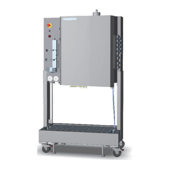
- Page 1 OligoPilot 400 Operating Instructions Original instructions Translation disc included cytiva.com...
-
Page 2: Table Of Contents
Safety instructions ..................... 10 Safety precautions ............................11 Labels ................................. 23 Emergency procedures ..........................27 System description .................... 32 Overview ................................33 Illustrations of OligoPilot 400 ........................34 System components ............................. 42 3.3.1 Cabinet purging system ..........................43 3.3.2 System pumps ............................... 45 3.3.3... - Page 3 Regulatory statements ..........................141 8.5.6 Declaration of Hazardous Substances (DoHS) ................142 8.5.7 Notification - products containing mercury ..................144 8.5.8 Other regulations and standards ......................145 Health and Safety Declaration Form ...................... 147 Index ........................... 149 OligoPilot 400 Operating Instructions 28960368 AH...
-
Page 4: Introduction
This chapter contains important user information, descriptions of safety notices, intended use of OligoPilot™ 400, and lists of associated documentation. In this chapter Section See page Important user information About this manual Associated documentation OligoPilot 400 Operating Instructions 28960368 AH... -
Page 5: Important User Information
OligoPilot 400 is intended for process development, small and pilot scale production of DNA and RNA oligonucleotides. OligoPilot 400 shall not be used in any clinical procedures, or for diagnostic purposes. WARNING Do not operate the product in any other way than described in the user documentation. - Page 6 Notes and tips Note: A note is used to indicate information that is important for trouble-free and optimal use of the product. Tip: A tip contains useful information that can improve or optimize your proce- dures. OligoPilot 400 Operating Instructions 28960368 AH...
-
Page 7: About This Manual
The Operating Instruction manual provides information needed to install, operate and maintain the product in a safe way. Scope of this manual This Operating Instruction manual is valid for OligoPilot 400. Typographical conventions Software items are identified in the text by bold italic text. -
Page 8: Associated Documentation
System documentation In addition to the Operating Instructions, the documentation package supplied with OligoPilot 400 also includes detailed specifications and traceability documents. The following table provides examples of technical specification documents that can be found in the documentation package delivered with the product. - Page 9 • The Online help contains dialog descriptions for UNICORN. The Online help is accessed from the Help menu. Component documentation Documentation for components produced both by Cytiva and by a third-party are, if existent, also included in the documentation package. OligoPilot 400 Operating Instructions 28960368 AH...
-
Page 10: Safety Instructions
2 Safety instructions Safety instructions About this chapter This chapter describes safety precautions, labels and symbols that are attached to OligoPilot 400. In addition, the chapter describes emergency and recovery procedures. In this chapter Section See page Safety precautions Labels... -
Page 11: Safety Precautions
WARNING Do not operate the product in any other way than described in the user documentation. OligoPilot 400 Operating Instructions 28960368 AH... - Page 12 WARNING Accessories. Use only accessories supplied or recommended by Cytiva. CAUTION Waste tubes and containers must be secured and sealed to prevent accidental spillage. OligoPilot 400 Operating Instructions 28960368 AH...
-
Page 13: Flammable Liquids And Explosive Environment
Explosion hazard: Make sure that the power to the process system is turned off when packing and connecting the column. WARNING Explosion hazard: Service or Maintenance of OligoPilot 400 must be performed in a non-classified area. OligoPilot 400 Operating Instructions 28960368 AH... -
Page 14: Personal Protection
Follow local and/or national regulations for safe operation and maintenance of this product. OligoPilot 400 Operating Instructions 28960368 AH... -
Page 15: Installing And Moving
WARNING System lifting. OligoPilot 400 shall only be lifted using the lower part of the supporting frame. OligoPilot 400 is not equipped with lifting eyebolts or telphers for hoist lift. - Page 16 The product is designed for indoor use only. CAUTION Packing crates may have been exposed to pesticides, depending on the regulations of the country of delivery. Recycle packing crates according to local recommendations for pesticide-treated wood. OligoPilot 400 Operating Instructions 28960368 AH...
-
Page 17: Power Supply
2 Safety instructions 2.1 Safety precautions Power supply WARNING OligoPilot 400 must always be connected to a grounded power outlet. WARNING Before connecting the power cord make sure that the supply voltage at the wall outlet corresponds to the marking on the equip- ment. -
Page 18: System Operation
120 V. CAUTION Connection of an external UPS for system operation shall only be performed by authorized personnel to avoid mismatching or connection errors. Contact your local Cytiva representative for more information. System operation WARNING Before starting to use the system, make sure that there are no unintentional leakages in the system or in connections to it. - Page 19 Never block the waste outlet, for instance with stop plugs, since this will create over-pressure and might result in injury. CAUTION Make sure that waste containers are dimensioned for maximum possible volume when the instrument is left unattended. OligoPilot 400 Operating Instructions 28960368 AH...
-
Page 20: Maintenance
OligoPilot 400 is properly decontaminated and sanitized before maintenance or service. WARNING All repairs should be done by service personnel authorized by Cytiva. Do not open any covers or replace parts unless specifically stated in the user documentation. WARNING Always disconnect power from OligoPilot 400 before performing any maintenance task. - Page 21 WARNING Only spare parts and accessories that are approved or supplied by Cytiva may be used for maintaining or servicing OligoPilot 400. WARNING Decontaminate the equipment before decommissioning to ensure that hazardous residues are removed.
- Page 22 2 Safety instructions 2.1 Safety precautions WARNING After assembly, the piping system must be tested for leakage at maximum pressure for continued protection against injury risks due to fluid jets, burst pipes or explosive atmosphere. OligoPilot 400 Operating Instructions 28960368 AH...
-
Page 23: Labels
OligoPilot 400. System label The image below shows an example of a system label. The OligoPilot 400 system label is located on the upper part of the rear panel of the process system. The label states the general specifications for OligoPilot 400. - Page 24 2 Safety instructions 2.2 Labels Label text Description System no.: Identifies the (unique) system installation. Code no.: Identifies the system as being an OligoPilot 400. Serial no. Cytiva serial number Year of manufacture: Year of manufacturing Supply voltage: Supply voltage...
- Page 25 Note: It is only the OligoPilot 400 process system that is classified. The Junction box and the computer must be located in a non-hazardous area. See...
- Page 26 Upon low pressure alarm immediately re- establish correct pressure or disconnect power. The safety label is attached to the front and back of the Process Cabinet. OligoPilot 400 Operating Instructions 28960368 AH...
-
Page 27: Emergency Procedures
2.3 Emergency procedures Emergency procedures Introduction This section describes how to perform an emergency shutdown of OligoPilot 400, the result in the event of power failure, and the procedure for restarting OligoPilot 400 in this case. Precautions WARNING Emergency shutdown may result in high pressures remaining in the system flow path. - Page 28 • Data and run status may be lost. switch off the circuit breaker to the fixed • Any external media supply, for example power supply. acetonitrile, is stopped immediately preventing explosive liquids from leaking out. • All valves will shut immediately. OligoPilot 400 Operating Instructions 28960368 AH...
- Page 29 Safety system for external media supply OligoPilot 400 has a safety system to which the external media supply at the plant should be connected. The safety system includes a relay in the junction box which trips and automatically shuts off the media supply when the emergency stop is pressed and also if any of the following conditions occur: •...
- Page 30 UNICORN computer, network printers and servers the following occurs: • The UNICORN computer with UniNet connection to the process system continues to run without interruption. • Other network equipment might be affected. OligoPilot 400 Operating Instructions 28960368 AH...
- Page 31 UPS units are not included in the delivery. Cytiva can however provide recommendations. Restart after emergency shutdown or power failure Follow the instructions below to restart OligoPilot 400 after emergency shutdown or power failure. Step Action Check that the compressed air supply is turned on.
-
Page 32: System Description
3 System description System description About this chapter This chapter provides a description of OligoPilot 400 and an overview of its compo- nents, including the UNICORN control system. In this chapter Section See page Overview Illustrations of OligoPilot 400 System components... -
Page 33: Overview
Before the actual process, the inlet tubing is purged with the appropriate reagents and solvents. During the process, several washing steps are included between the reaction steps above. These steps ensure that no residual reagent from the previous step inter- feres with the next reaction step. OligoPilot 400 Operating Instructions 28960368 AH... -
Page 34: Illustrations Of Oligopilot 400
3 System description 3.2 Illustrations of OligoPilot 400 Illustrations of OligoPilot 400 Introduction The main features and components for OligoPilot 400 are indicated in this section. System overview The illustration below shows a front view of the system with all options. Part... - Page 35 Part Function Description Valve Column Inlet Valve XV-051 Valve Reagent Valve Pump P-201 B XV-023 Valve Reagent Valve Pump P-201 B XV-022 Valve Reagent Valve Pump P-201 A XV-021 Valve Column Outlet Valve XV-052 OligoPilot 400 Operating Instructions 28960368 AH...
- Page 36 Pumps and Sensors The illustration below shows the pumps and sensors within the Process Cabinet. The illustration is located at the front of the Process Cabinet with the door open. Part Function Pump P-201 A OligoPilot 400 Operating Instructions 28960368 AH...
- Page 37 Front door of Process Cabinet UV cell AE-131 Conductivity cell CE/TE-101 Pressure sensor PT-111 Junction box The illustration below shows the front of the Junction box with all options. PURGE ALARM POWER ON MAINS SWITCH SERVICE SWITCH OligoPilot 400 Operating Instructions 28960368 AH...
- Page 38 1= Service mode (no purge required) 0= Off 2= Normal mode (purge required) WARNING Explosion hazard: Service or Maintenance of OligoPilot 400 must be performed in a non-classified area. Note: The key should only be inserted when there is a service planned and the area is EX safe.
- Page 39 SERVICE Junction box Used by service to power the system SWITCH (switch) without purging. Black MAINS SWITCH Junction box Turns power on/off to the junction box (switch) and the process system. OligoPilot 400 Operating Instructions 28960368 AH...
- Page 40 Optical Ethernet communication from junction box. Inert gas inlet connection. Purge control signal to the junction box. Optical PROFIBUS™ industry standard communication to the junction box. Solvent control valve (to safety system for external media supply). OligoPilot 400 Operating Instructions 28960368 AH...
- Page 41 Pneumatic signal for cabinet purge completed Ethernet communication from the computer External signals Optical PROFIBUS communication Optical Ethernet communication with the system Power supply from the junction box to the system Mains power supply to the communication junction box OligoPilot 400 Operating Instructions 28960368 AH...
-
Page 42: System Components
3 System description 3.3 System components System components About this chapter This chapter provides an overview of the system components of OligoPilot 400. In this section Section See page 3.3.1 Cabinet purging system 3.3.2 System pumps 3.3.3 Meters and sensors 3.3.4... -
Page 43: Cabinet Purging System
After the system cabinet has been successfully purged, voltage is supplied to the system as well. Overriding this interlock is only possible by using the service switch. Purging modes The purging system operates in two modes: OligoPilot 400 Operating Instructions 28960368 AH... - Page 44 If the purging system fails maintain the specified overpres- sure in the cabinet, an alarm is issued in UNICORN, the system sets to Pause and the safety system shuts off the external media supply. OligoPilot 400 Operating Instructions 28960368 AH...
-
Page 45: System Pumps
Each pump head is equipped with check valves at the system flow inlet and outlet, and at the rinsing flow outlet. The pumps shown in the following illustration are located on the front of the cabinet. Part Function Pump P-202 Pump P-201 B OligoPilot 400 Operating Instructions 28960368 AH... - Page 46 P-201B P-201A Flow rate 800 mL/min 400 mL/min Note: P-907 and P-908 together can produce a total flow rate up to 1200 mL/min. Pressure 0 to 15 bar 0 to 15 bar range OligoPilot 400 Operating Instructions 28960368 AH...
- Page 47 The piston rinsing system tubing is connected to the rearmost holes on the pump heads. The following flow diagram shows the tubing configuration of the piston rinsing system. P-907 P-908 Part Function Rinsing solution acetonitrile Three-port valve Three-port valve OligoPilot 400 Operating Instructions 28960368 AH...
-
Page 48: Meters And Sensors
3.3.3 Meters and sensors Meters OligoPilot 400 is equipped with detectors for continuous inline measurement of conductivity, temperature and UV absorbance, as well as pressure sensors. The flow cells are connected close together, which minimizes band broadening and time delay between the detectors. The flow cells are easily accessible from the front panel to facilitate maintenance. - Page 49 The wavelength can be changed using the UNICORN software during a run, either from the method or by manual instruction. The optical path length, 1, 2 or 5 mm, is set with shim plates. The default is 2 mm. OligoPilot 400 Operating Instructions 28960368 AH...
- Page 50 The third pressure sensor (PT-111) is located after the column. The pressure range is 0 to 25 bar (2.5 MPa, 362 psi). Part Function Pressure sensor PT-201 Pressure sensor PT-111 located after the column OligoPilot 400 Operating Instructions 28960368 AH...
- Page 51 UV cell. The backpressure can be controlled in two ways, either by defining a valve position in percentage or by defining a desired backpressure value. Refer to helptexts in Software Configuration Description for details. OligoPilot 400 Operating Instructions 28960368 AH...
-
Page 52: Valves
Valves Valve blocks The flow path in OligoPilot 400 is controlled by stepper motor actuated membrane valves. The valves are located in a total of nine valve blocks. The valve blocks have different configurations of inlet and outlet ports depending on where they are located in the flow path. -
Page 53: Tubing
Reagents, solvents and cleaning solutions, are introduced into the system through inlet valves via the manifold. The flow exits the system flow path through an outlet valve and the manifold. See Section 3.6 Flowchart, on page OligoPilot 400 Operating Instructions 28960368 AH... -
Page 54: Cooler
On top of the system cabinet there is a cooler exhaust. The cooler is set to keep the temperature below 40°C inside the cabinet. The outcoming air is hot. To avoid heating the process room, this exhaust can be connected to the ventilation system (elephant trunk). OligoPilot 400 Operating Instructions 28960368 AH... -
Page 55: Power And Communication Connections
The optical cables between the process cabinet and the junction box should be installed with mechanical protection. Note: The optical fiber cables have a permissible bend radius of 65 mm. Smaller bend radius might damage the cable fibre. OligoPilot 400 Operating Instructions 28960368 AH... - Page 56 Communication cable to computer External signal cable Power supply cable via MAINS SWITCH on junction box Ethernet communication cables (optical) PROFIBUS communication cable (optical) OD air hose, 6 mm OligoPilot 400 Operating Instructions 28960368 AH...
- Page 57 System behavior during loss of pressure If the pressure supply to OligoPilot 400 reaches critically low levels, the system will go into pause and trigger an alarm in UNICORN which will return the following error on the display: No Air Supply!.
-
Page 58: Inert Gas Delivery System
The auxiliary gas outlet (2 to 3 bar) is used for unpacking the column, and for flushing and filling the system flow path. The gas outlet is located above the column, and the gas flow is manually adjusted by turning the gas valve knob next to the outlet. OligoPilot 400 Operating Instructions 28960368 AH... - Page 59 3 System description 3.3 System components 3.3.8 Inert gas delivery system OligoPilot 400 Operating Instructions 28960368 AH...
-
Page 60: Containers For Reagents And Solvents
The stand includes a tray that collects any leakage from the containers. In case of leakage, a built-in liquid sensor in the tray raises an alarm, which causes the safety system to pause the run and to shut off the external media supply. OligoPilot 400 Operating Instructions 28960368 AH... -
Page 61: Columns
Columns Small scale columns OligoPilot 400 is intended to be used with small scale production columns, such as FineLINE™ 35 oligo column, Adjustable Oligo column, FineLINE 70 and FineLINE 100. Columns suitable to be used with the system also includes AxiTide™ 50 and AxiTide 140. -
Page 62: Flowchart
1 2 3 4 XV-051 XV-001 XV-002 XV-003 XV-021 XV-022 XV-023 4 3 2 1 4 3 2 1 4 3 2 1 4 3 2 1 4 3 2 1 4 3 2 1 OligoPilot 400 Operating Instructions 28960368 AH... - Page 63 Acetonitrile Detritylation solution Oxidation reagent Activator Extra 1 Thiolation reagent Capping A Capping B Stop Stop Stop Waste (W1) Pressure sensor PT-202 Pump P-202 Pressure sensor PT-201 Pumps P-201 A and P-201 B Amidites OligoPilot 400 Operating Instructions 28960368 AH...
-
Page 64: Unicorn Control System
3.7 UNICORN control system UNICORN control system UNICORN is a complete software for control and supervision of OligoPilot 400. The software runs under Microsoft® Windows® operating system. UNICORN is supplied with a number of ready-made method templates that provide creation of methods for synthesis. -
Page 65: Installation
4 Installation Installation About this chapter This chapter provides required information to enable users and service personnel to unpack, install, move and transport OligoPilot 400. In this chapter Section See page Unpacking and transport Setup Installation procedure Precautions WARNING Explosion hazard:Read and understand all precautions in the... - Page 66 A fume hood or similar ventilation system shall be installed when flammable or noxious substances are used. WARNING The product must be installed and prepared by Cytiva personnel or a third party authorized by Cytiva. WARNING The customer must make sure that all installation, maintenance,...
- Page 67 The power cord must always be easy to disconnect. WARNING Always disconnect power from the OligoPilot 400 instrument before an instrument module is removed or installed, or a cable is connected or disconnected. NOTICE Do not touch the tips of the optical fiber with anything other than lens paper.
-
Page 68: Unpacking And Transport
Type Particle and oil free, non condensing For details, see the General specification in the system documentation package. Unpacking The equipment should always be unpacked by a Cytiva representative. During unpacking of the system: OligoPilot 400 Operating Instructions 28960368 AH... - Page 69 Report any damage to your local Cytiva representative. • Check that all equipment is enclosed in the crate according to the packing list supplied. Connections The following connections must be in place before to OligoPilot 400 can be used: • Compressed air • Inert gas • Power •...
-
Page 70: Setup
4 Installation 4.2 Setup Setup About this section This section describes the steps that need to be taken to set up OligoPilot 400 before use. Precautions WARNING Explosion hazard: Avoid discharge from static electricity when working in potentially explosive atmospheres by: •... - Page 71 4 Installation 4.2 Setup Raise the cabinet Raise the cabinet when the system is in position inside the fume hood. Follow the instruction below to raise the cabinet. OligoPilot 400 Operating Instructions 28960368 AH...
- Page 72 • Check that all cables between the system and the junction box are connected and secured. For an illustration of the connections, see Illustration, on page • Check that UNICORN is installed on the computer. OligoPilot 400 Operating Instructions 28960368 AH...
-
Page 73: Installation Procedure
UNICORN. Note: Enabled antivirus programs can cause the communication with OligoPilot 400 to fail. Sometimes re-installation of UNICORN might even be necessary if the antivirus program is installed or enabled after setting up the communication during installation. Compressed air/inert gas Check that: •... - Page 74 CAUTION Use ONLY tubing supplied by Cytiva to make sure that the pressure specifications of the tubing are met. • Check that tubing for reagents, solvents and product collection are properly fitted to the correct inlet and outlet connections on the process system (see Product Documentation for tubing drawings).
- Page 75 100%, set a flow on all pumps and lower the full flow set-point until pressure starts to build up in the system. Use this value + 5% as full flow set-point (MaxPos). OligoPilot 400 Operating Instructions 28960368 AH...
- Page 76 The instruction is to tighten the screws evenly until the valve membrane balloons out a little bit. It is because of that each valve can be slightly different. OligoPilot 400 Operating Instructions 28960368 AH...
-
Page 77: Operation
5 Operation Operation About this chapter This chapter provides the information required to safely operate OligoPilot 400. In this chapter Section See page Prepare the system Column packing procedure Perform a run Procedures after a run Precautions • General precautions, on page 11 •... - Page 78 NOTICE Running out of inert gas can seriously affect the flow performance of OligoPilot 400 and therefore jeopardize the run. Check the pres- sure gauges and the feed tank regularly. NOTICE Water will seriously damage the result of an oligonucleotide synthesis.
-
Page 79: Prepare The System
5 Operation 5.1 Prepare the system Prepare the system Introduction This section describes the steps that needs to be performed to prepare OligoPilot 400 for a run. Precautions WARNING The product must be installed and prepared by Cytiva personnel or a third party authorized by Cytiva. - Page 80 Switch off the inert gas supply on the system corresponding to the reagent before opening a bottle cap and replacing the bottle. Prerequisites Before OligoPilot 400 is taken into operation, make sure that all relevant procedures in Chapter 4 Installation, on page 65 have been performed.
- Page 81 The pre-purging procedure of the process cabinet starts. When successfully finished, the green POWER indicator on the junction box turns on. Note: If a UPS is used for the computer and OligoPilot 400, the UPS must be turned on before any other equipment. OligoPilot 400 Operating Instructions 28960368 AH...
- Page 82 If you log on for the very first time, select default and enter the password default. Click OK. In the System Control module, select System →Connect. In the dialog shown, select the appropriate system name and click OK. The system name is specified during installation configuration. OligoPilot 400 Operating Instructions 28960368 AH...
- Page 83 When changing the inert gas cylinder, make sure that there is no condensation in the regulator or gas tubing. Flush the regulator with inert gas from the new cylinder before connecting to OligoPilot 400. An appro- priate pressure is 0.1 to 0.2 bar.
- Page 84 5 Operation 5.1 Prepare the system AxiTide 50 and AxiTide140 are manufactured to custom order and have individual product codes. Contact your local Cytiva representative for further information. OligoPilot 400 Operating Instructions 28960368 AH...
-
Page 85: Column Packing Procedure
WARNING Only use columns that withstand expected pressures. If not, the column might rupture, resulting in injury. OligoPilot 400 Operating Instructions 28960368 AH... - Page 86 Clean the column according to the local standard operating procedure (SOP). Make sure that the power to OligoPilot 400 is purged and On. Make a Primer Support slurry with the amount of support needed for the intended synthesis scale. Make the slurry in approximately 500 mL (FineLINE 70) or 1000 mL (FineLINE 100) of acetonitrile.
- Page 87 Mark the piston with a marker pen at a distance from the top of the piston equal to the bed height (a). Lock the column vertically in the OligoPilot 400 column holder. Connect the earth cable between the column and the system housing.
- Page 88 Note: Make sure that the ventilation tube is not restricted or blocked. Wet the column adapter O-ring with acetonitrile or ethanol. OligoPilot 400 Operating Instructions 28960368 AH...
- Page 89 Check that the column inlet ball valve (1) is open and that the tubing from the ball valve at the column outlet (2) goes to XV-052 via the PT-111 pres- sure sensor. Open ball valve (1) at column inlet and ball valve (2) at column outlet. OligoPilot 400 Operating Instructions 28960368 AH...
-
Page 90: Perform A Run
• The waste container is not full and will accept the volume diverted to it during the run. • The the front door on OligoPilot 400 is closed. • All the tubing connectors are tight to avoid leakage during the run. - Page 91 See the UNICORN user manuals for the following instructions: • How to start a synthesis run. • How to view a run and customize the view panes. • How to view and print the result. OligoPilot 400 Operating Instructions 28960368 AH...
-
Page 92: Procedures After A Run
5.4 Procedures after a run Procedures after a run In this section Section See page 5.4.1 Unpack the column 5.4.2 Procedures after a run Precautions NOTICE Avoid condensation by letting the unit equilibrate to ambient temperature. OligoPilot 400 Operating Instructions 28960368 AH... -
Page 93: Unpack The Column
Preparations Step Action Switch off the power to OligoPilot 400. Close column inlet (1) and outlet ball valves (2). Disconnect inlet tubing 25 and outlet tubing 24 on the valve side of the ball valves (at 1 and 2). Refer to Section 3.6 Flowchart, on page 62... - Page 94 Place a beaker or similar vessel with capacity for at least 2 CV (column volume) upside down over the top of the column. The beaker should be wide enough to fit around the outside of the column. Turn the column upside down. OligoPilot 400 Operating Instructions 28960368 AH...
- Page 95 (the “puck method”). Note: Hold the beaker securely, since the support will come out with high speed from the column. Stop the inert gas when unpacking is finished. OligoPilot 400 Operating Instructions 28960368 AH...
-
Page 96: Procedures After A Run
For detailed description of deprotection refer to Cytiva user manuals and application notes for oligonucleotide synthesis. For post deprotection, wash the support with 1 CV ethanol/water followed by 1 CV water. For detailed description refer to Cytiva user manuals and application notes for oligonucleotide synthesis. OligoPilot 400 Operating Instructions 28960368 AH... -
Page 97: Maintenance
About this chapter Regular maintenance is important for safe and trouble-free operation of OligoPilot 400. The user should perform daily and monthly maintenance. Preventive maintenance should be performed on a yearly basis by qualified service personnel. This chapter provides instructions for user maintenance and for replacing spare parts. - Page 98 If any reagents or solvents are ingested, consult a physician immedi- ately. WARNING Only properly trained personnel may operate and maintain the product. OligoPilot 400 Operating Instructions 28960368 AH...
- Page 99 6 Maintenance WARNING All repairs should be done by service personnel authorized by Cytiva. Do not open any covers or replace parts unless specifically stated in the user documentation. WARNING Always use appropriate Personal Protective Equipment (PPE) during operation and maintenance of this product.
- Page 100 After assembly, the piping system must be tested for leakage at maximum pressure for continued protection against injury risks due to fluid jets, burst pipes or explosive atmosphere. WARNING For continued protection from fire hazard, replace only with same type and rating of fuse. OligoPilot 400 Operating Instructions 28960368 AH...
-
Page 101: User Maintenance Schedule
If there is sign of liquid leaking between a pump head and the system panel, or increased or decreased volume of rinsing solution, contact Cytiva represen- tative to replace the piston assembly, ceramic tube, and/or O-rings in the pump head. - Page 102 Replacing the outer check valves, on page 108 more information. Clean the rinsing system check valve. Tubing connec- Replace the tubing and Tubing and connectors, on page 103. tors ferrule. OligoPilot 400 Operating Instructions 28960368 AH...
-
Page 103: Component Maintenance
Always use new tubing and ferrules. Tubing and ferrules that have been used or disconnected should not be re-used. Spare parts and accessories For correct up to date information on spare parts and accessories, contact Cytiva. OligoPilot 400 Operating Instructions 28960368 AH... -
Page 104: Pumps
If there are signs of liquid leaking between the pump head and the housing side panel, or the volume of the rinsing solution has increased or decreased, contact a Cytiva representative to replace the piston assembly, liquid chamber and/or ceramic tube including O-rings of the leaking pump head. - Page 105 Torque 3 to 3.5 Nm Check valve inner (rinsing system) Torque 3 to 3.5 Nm Piston Screw (2 pcs.) Torque 2.5 Nm Remove the old piston assembly Step Action Turn off the system power. OligoPilot 400 Operating Instructions 28960368 AH...
- Page 106 Loosen the screws crosswise, half a turn at a time, while pushing firmly on the front face of the pump head to compensate for the pressure of the piston return spring. Carefully pull out the pump head and place it face down on the bench. OligoPilot 400 Operating Instructions 28960368 AH...
- Page 107 Carefully remove and discard the old rinse chamber O-ring. Insert a new O-ring (thin). Lift off the liquid chamber. Carefully remove and discard the old pump head front O-ring. Insert a new O-ring (thick). OligoPilot 400 Operating Instructions 28960368 AH...
- Page 108 Use the two wrenches to remove the metal nut of the check valve from the adapter. Note the direction of the tube inside the adapter; the round hole faces the rinse chamber. Use a wrench to remove the adapter from the rinse chamber. OligoPilot 400 Operating Instructions 28960368 AH...
- Page 109 Carefully slide the ceramic tube onto the piston. Make sure that the tube end that has the largest bevel cutting on the inner edge faces the rinsing system chamber. Insert the ceramic tube with the piston into the liquid chamber. OligoPilot 400 Operating Instructions 28960368 AH...
- Page 110 Mount the complete pump head over the locating pins on the front panel. Press firmly on the pump head front and use the hex key to fit and tighten the two retaining screws crosswise a little at a time. OligoPilot 400 Operating Instructions 28960368 AH...
- Page 111 If a leakage occurs, immediately switch off the system before taking care of the leakage. Step Action Connect the outlet tubing between the outlet check valve and the manifold block. See Section 3.6 Flowchart, on page OligoPilot 400 Operating Instructions 28960368 AH...
- Page 112 6.2 Component maintenance 6.2.1 Pumps Step Action Connect the inlet tubing to the inlet check valve. Connect the rinsing system tubing. See Section 3.6 Flowchart, on page The pump is ready to be primed. OligoPilot 400 Operating Instructions 28960368 AH...
-
Page 113: Membrane Valve Block
• Two persons are required to replace the wetted parts of the valve block. • Lubricant PTFE S128 (spare part number 18686901) is recommended. Illustration Part Function Membrane Connection block Valve seat Drain holes OligoPilot 400 Operating Instructions 28960368 AH... - Page 114 Disconnect all tubing from the valve. Remove the six attachment screws using the wrench. Carefully loosen the old connection block. Pull out and discard the old membranes. Note: Be careful not to scratch the mechanical housing of the valve. OligoPilot 400 Operating Instructions 28960368 AH...
- Page 115 Make sure that the marking on all blocks (Oligo 1, Oligo 2, Oligo 3, Oligo 4) can be read the right way round. This will make sure that the drainholes in the valve blocks face downwards. Connect the tubing. OligoPilot 400 Operating Instructions 28960368 AH...
- Page 116 6 Maintenance 6.2 Component maintenance 6.2.2 Membrane valve block Step Action Disable SetValvePosition under Settings/Specials. The valves will return to their normal positions. OligoPilot 400 Operating Instructions 28960368 AH...
-
Page 117: Pcv Valve
• IP converter controlling the PCV-341 is malfunctioning. • The backpressure valve PCV-341 is malfunctioning. Contact your Cytiva representative to repair or replace these components if found faulty or for further troubleshooting as required. OligoPilot 400 Operating Instructions 28960368 AH... -
Page 118: Cleaning
Copy the form you need from Section 8.6 Health and Safety Declaration Form, on page or print it from the PDF file available on the User Documentation CD. OligoPilot 400 Operating Instructions 28960368 AH... -
Page 119: Storage
6 Maintenance 6.4 Storage Storage Introduction This section describes how to prepare OligoPilot 400 for both short term (up to one month) and for long term storage. Storage procedure Step Action Disconnect amidite, activator, oxidation, Capping A, Capping B and Beau- cage bottles. -
Page 120: Troubleshooting
• Old reagents. Amidites older than 2 to 4 weeks. Normally G-amidite is more sensi- tive than others. T-amidite is the least sensitive. • Not enough of, or no purge of amidites and/or solvents prior to the synthesis. OligoPilot 400 Operating Instructions 28960368 AH... - Page 121 4 Flush with water and acetonitrile. 5 Repeat the procedure if necessary. Tip: If nitric acid is unavailable, it is possible to use Hell- manex™ III to clean the UV cell. Follow the appropriate manufacturer's user instructions. OligoPilot 400 Operating Instructions 28960368 AH...
- Page 122 Blockage or partial Flush through to clear blockage. blockage of flow path. If necessary, replace tubing. Abnormal The IP converter control- Check, repair and/or replace as required. ling the PCV-341 is column back- pressure malfunctioning. OligoPilot 400 Operating Instructions 28960368 AH...
- Page 123 Make sure that the valve alarm settings are enabled to be able to detect valve issues. Low reagent Bad piston spring. Disassemble the pump head and examine the piston flow and noise. spring. Replace the piston assembly, if necessary. OligoPilot 400 Operating Instructions 28960368 AH...
- Page 124 Change the valve membrane. See Section 6.2.2 be damaged. Membrane valve block, on page 113. Pressure sensors Error Problem Corrective action symptom External Leaking tubing connec- Check the tubing connectors. Tighten or replace if leakage. tors. necessary. OligoPilot 400 Operating Instructions 28960368 AH...
- Page 125 Corrective action symptom The specified The rear door is not Close the door. pressure in the closed. cabinet cannot The compressed air Check the air supply to the system. be maintained. supply is not sufficient. OligoPilot 400 Operating Instructions 28960368 AH...
-
Page 126: Reference Information
8 Reference information Reference information About this chapter This chapter provides reference information that may become useful when installing, operating, maintaining and troubleshooting OligoPilot 400. In this chapter Section See page Specifications Chemical resistance Recommended reagents Recycling information Regulatory information... -
Page 127: Specifications
8 Reference information 8.1 Specifications Specifications Introduction This section contains technical data pertaining to OligoPilot 400 and its components. For complete technical data, refer to the Product Documentation. Technical specification Parameter Specification Ingression protection IP55 Supply voltage 110 to 230 V AC... - Page 128 Lens P-201 A Pump head Pump Head P-201 B Ceramic Tube O-ring Sealing Valve housing Ball stopper Ruby ball Lower lid PT-201 Pressure sensor PT-202 FT-141 Flow meter FT-142 HV-303 Manual (hand) Diaphragm valve OligoPilot 400 Operating Instructions 28960368 AH...
-
Page 129: Chemical Resistance
8.2 Chemical resistance Chemical resistance Introduction to chemical resistance This section gives some general guidelines concerning chemical resistance for OligoPilot 400 components. Regarding exposure to solutions not covered by these guidelines, contact your Cytiva representative for recommendations. Flow Path Chemical... - Page 130 Silicone not resistant. Pres- sure limit for PEEK decreases. Hydrochloric 7647-01-0/231-5 Silicone not acid, 0.1 M 95-7 resistant. Hydrochloric Avoid Silicone not acid, > 0.1 M resistant. Tita- nium is affected by long term use. OligoPilot 400 Operating Instructions 28960368 AH...
- Page 131 Sodium bisul- phate Sodium borate Sodium carbo- nate Sodium chloride 7647-14-5/231-5 98-3 Sodium Avoid 1310-73-2/215-1 PVDF and borosi- hydroxide, 2 M 85-5 licate glass are affected by long term use. Sodium sulphate 7757-82-6/231-8 20-9 OligoPilot 400 Operating Instructions 28960368 AH...
- Page 132 ETFE, CTFE, PP and PE are not resistant. Toluene Trichloroacetic 76-03-9/200-927 acid, 1% Trifluoroacetic 176-05-1/200-92 acid, 1% Urea, 8M 57-13-6/200-315 o-Xylene and p- Avoid PP and PE are Xylene affected by long term use. OligoPilot 400 Operating Instructions 28960368 AH...
-
Page 133: Recommended Reagents
108-88-3 Dichloroacetic acid 79-43-6 5-Benzylmercaptotetrazole 21871-47-6 For other reagent mixtures contact Cytiva for advice on chemical compatibility. Note: Before usage of reagents and reagent mixtures, the Intellectual Property (IP) situation should always be investigated. OligoPilot 400 Operating Instructions 28960368 AH... -
Page 134: Recycling Information
Waste electrical and electronic equipment must not be disposed of as unsorted munic- ipal waste and must be collected separately. Please contact an authorized representa- tive of the manufacturer for information concerning the decommissioning of the equipment. OligoPilot 400 Operating Instructions 28960368 AH... -
Page 135: Regulatory Information
European Union and European Economic Area 8.5.3 Eurasian Economic Union Евразийский экономический союз 8.5.4 Regulations for North America 8.5.5 Regulatory statements 8.5.6 Declaration of Hazardous Substances (DoHS) 8.5.7 Notification - products containing mercury 8.5.8 Other regulations and standards OligoPilot 400 Operating Instructions 28960368 AH... -
Page 136: Contact Information
The table below summarizes the required manufacturing information. Requirement Information Name and address of manufacturer Cytiva Sweden AB Björkgatan 30 SE 751 84 Uppsala Sweden Telephone number of manufacturer + 46 771 400 600 OligoPilot 400 Operating Instructions 28960368 AH... -
Page 137: European Union And European Economic Area
• used according to the Operating Instructions or user manuals, and • used in the same state as it was delivered, except for alterations described in the Operating Instructions or user manuals. OligoPilot 400 Operating Instructions 28960368 AH... -
Page 138: Eurasian Economic Union
импортере В следующей таблице приводится сводная информация о производителе и импортере, согласно требованиям Технических регламентов Таможенного союза и (или) Евразийского экономического союза. Требование Информация Информацию об изготовлении Наименование, адрес и номер См. телефона производителя OligoPilot 400 Operating Instructions 28960368 AH... - Page 139 Member States of the Customs Union of the Eurasian Economic Union Данный знак о Евразийском соответствии указывает, что изделие одобрено для использования на рынках государств-членов Таможенного союза Евразийского экономического союза OligoPilot 400 Operating Instructions 28960368 AH...
-
Page 140: Regulations For North America
Note: The user is cautioned that any changes or modifications not expressly approved by Cytiva could void the user’s authority to operate the equip- ment. This equipment has been tested and found to comply with the limits for a Class A digital device, pursuant to part 15 of the FCC Rules. -
Page 141: Regulatory Statements
This section shows regulatory statements that apply to regional requirements. EMC emission, CISPR 11: Group 1, Class A statement NOTICE This equipment is not intended for use in residential environments and may not provide adequate protection to radio reception in such environments. OligoPilot 400 Operating Instructions 28960368 AH... -
Page 142: Declaration Of Hazardous Substances (Dohs)
Periodic replacement of those consumables or parts to maintain the declared EFUP shall be done in accordance with the Product Maintenance Procedures. This product must not be disposed of as unsorted municipal waste, and must be collected sepa- rately and handled properly after decommissioning. OligoPilot 400 Operating Instructions 28960368 AH... - Page 143 Indicates that this hazardous substance contained in at least one of the homogeneous materials used for this part is above the limit requirement in GB/T 26572 • Data listed in the table represents best information available at the time of publication. OligoPilot 400 Operating Instructions 28960368 AH...
-
Page 144: Notification - Products Containing Mercury
• For safe handling procedures and the measures to be taken in case of accidental breakage, and for options available for disposal and recycling, please refer to https://www.ec.gc.ca/mercuremercury/Default.asp?lang=En&n=DB6D2996-1. If additional support is needed, please contact your Cytiva representative. • This product should be disposed of or recycled in accordance with the applicable laws. -
Page 145: Other Regulations And Standards
Explosive atmospheres - Explosion prevention and protection – Part 1: Basic concepts and methodology IEC/EN 60079-0 Explosive atmospheres - Part 0: Equipment – General Requirements. EN 60079-2 Explosive atmospheres - Part 2: Equipment protection by pressurized enclosure "p". OligoPilot 400 Operating Instructions 28960368 AH... - Page 146 8.5.8 Other regulations and standards Additional design considerations For additional design considerations, such as ASME-BPE, GMP and cGMPs information refer to the product-specific specification information provided in the documentation package delivered with each equipment. OligoPilot 400 Operating Instructions 28960368 AH...
-
Page 147: Health And Safety Declaration Form
Service Ticket #: To make the mutual protection and safety of Cytiva service personnel and our customers, all equipment and work areas must be clean and free of any hazardous contaminants before a Service Engineer starts a repair. To avoid delays in the servicing of your equipment, complete this checklist and present it to the Service Engineer upon arrival. - Page 148 To make sure the mutual protection and safety of Cytiva personnel, our customers, transportation personnel and our environment, all equipment must be clean and free of any hazardous contaminants before shipping to Cytiva. To avoid delays in the processing of your equipment, complete this checklist and include it with your return.
-
Page 149: Index
Pumps, 104 package, 8 Manifold, 34 software, 9 Manufacturing information, 136 Membrane valve, 124 Troubleshooting, 124 Meter, 48 Emergency, 27, 28 Procedures, 27 Shutdown, 28 Stop, 28 Notes and tips, 6 Emergency stop, 38, 39 OligoPilot 400 Operating Instructions 28960368 AH... - Page 150 134 Reference information, 126 Regulatory information, 135 Safety labels, 26 Safety notices, 6 Safety precautions, 11 Safety system media, 29 Site requirements, 68 Storage, 119 System, 127 dimensions, 127 specifications, 127 OligoPilot 400 Operating Instructions 28960368 AH...
- Page 151 Page intentionally left blank...
- Page 152 Standard Software End-User License Agreement is available on request. All goods and services are sold subject to the terms and conditions of sale of the supplying company operating within the Cytiva business. A copy of those terms and conditions is available on request. Contact your local Cytiva representative for the most current information.
Need help?
Do you have a question about the OligoPilot 400 and is the answer not in the manual?
Questions and answers