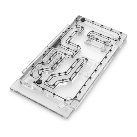
ekwb EK-Quantum Reflection2 PC-O11D EVO D5 PWM D-RGB User Manual
Distribution plate
Hide thumbs
Also See for EK-Quantum Reflection2 PC-O11D EVO D5 PWM D-RGB:
- User manual (16 pages) ,
- User manual (17 pages) ,
- User manual (15 pages)
Table of Contents
Advertisement
Quick Links
Advertisement
Table of Contents

Related Manuals for ekwb EK-Quantum Reflection2 PC-O11D EVO D5 PWM D-RGB


Summary of Contents for ekwb EK-Quantum Reflection2 PC-O11D EVO D5 PWM D-RGB
- Page 1 EK-Quantum Reflection PC-O11D EVO D5 PWM D-RGB DISTRIBUTION PLATE USER GUIDE...
- Page 2 The EK Fittings require only a small amount of force to screw them firmly in place since the liquid seal is ensured by the rubber O-ring gaskets. The use of corrosion inhibiting coolants is always recommended for any liquid cooling system. EKWB recommends any of the EKCryofuel for worry-free usage.
-
Page 3: Table Of Contents
TABLE OF CONTENT BOX CONTENTS DISTRIBUTION PLATE DIMENSIONS TECHNICAL SPECIFICATIONS AND PRODUCT PARTS PREPARING THE 011D EVO CHASSIS PREPARING AND INSTALLING THE DISTRIBUTION PLATE RECOMMENDED DISTRIBUTION PLATE CONFIGURATIONS ATTACHING THE PUSH-IN ADAPTER (OPTIONAL) FLOW DIAGRAM CONNECTING THE D-RGB LED STRIP CONNECTING THE PUMP TESTING THE LOOP SUPPORT AND SERVICE... -
Page 4: Box Contents
BOX CONTENTS Mounting Mechanism EAN: 105504 EK-Loop Multi Allen Key (1 pc) Screw M4x8 DIN7991 (2 pcs) Allen Key 2.5 mm (1 pc) Screw M3x8 DIN7991 (2 pcs) EK-Quantum Reflection PC-O11D EVO D5 PWM D-RGB Allen Key 2 mm (1 pc) - 4 -... -
Page 5: Distribution Plate Dimensions
DISTRIBUTION PLATE DIMENSIONS 207.3 mm 170.4 mm 161.2 mm 101.1 mm 171.9 mm 45.1 mm 71 mm 29 mm 137.4 mm 8 mm 44 mm 25.6 mm 57 mm 41.6 mm 85 mm 71.4 mm 100 mm 75.4 mm 170.4 mm - 5 -... -
Page 6: Technical Specifications And Product Parts
TECHNICAL SPECIFICATIONS AND PRODUCT PARTS Technical Specification: Dimensions with the attached pump (W x D x H): 207.3 x 75.4 x 405.2 mm – D-RGB LED count: 21 – D-RGB cable length: 500 mm – D-RGB connector standard 3-pin (+5V, Data, Blocked, Ground) Position Description Quantity... -
Page 7: Preparing The 011D Evo Chassis
PREPARING THE 011D EVO CHASSIS STEP 1 Unscrew the factory provided screws and remove the top panels from the case. STEP 1 STEP 2 Remove both side panels and the front panel from the case. STEP 2 - 7 -... -
Page 8: Preparing And Installing The Distribution Plate
PREPARING AND INSTALLING THE DISTRIBUTION PLATE STEP 1 Carefully place the distribution plate into the case and align the mounting holes. Be careful not to scratch the acrylic! STEP 1 STEP 2 Secure the distribution plate using the included M3 x 8 and M4 x 8 DIN7991 screws through the front frame of the case. -
Page 9: Recommended Distribution Plate Configurations
RECOMMENDED DISTRIBUTION PLATE CONFIGURATIONS To complete your loop, all ports must be used as marked in the TOP RADIATOR OUTLET image. (TRIPLE RADIATOR TOP RADIATOR OUTLET CONFIGURATION) All remaining unused ports must be closed with supplied plugs, (DUAL RADIATOR using the EK-Loop Multi Allen Key. FILL PORT CONFIGURATION) (DRAIN PORT... - Page 10 FILL PORT (DRAIN PORT IN FLIPPED CONFIG) DRAIN PORT (FILL PORT IN FLIPPED CONFIG) - 10 -...
-
Page 11: Attaching The Push-In Adapter (Optional)
ATTACHING THE PUSH-IN ADAPTER (OPTIONAL) The push-in adapters can be attached to the marked places in the diagram. OPTIONAL For easier installation of the push-in adapters, EK recommends to PUSH-IN lubricate the O-rings with a few drops of coolant or water. ADAPTER HOLES - 11 -... -
Page 12: Flow Diagram
FLOW DIAGRAM - 12 -... -
Page 13: Connecting The D-Rgb Led Strip
CONNECTING THE D-RGB LED STRIP Plug the 3-pin connector of the distribution plate D-RGB LED light to the D-RGB HEADER on the motherboard. The LED will work if the pin layout on the header is as follows: +5V, Digital, Empty, Ground. D-RGB Header RGB Header CONNECTING THE PUMP... -
Page 14: Testing The Loop
TESTING THE LOOP To make sure the installation of EK components was successful, we recommend you perform a leak test for 24 hours. When your loop is complete and filled with coolant, connect the pump to a PSU outside of your system. Do not connect power to any of the other components. -
Page 15: Support And Service
SUPPORT AND SERVICE In case you need assistance or wish to order spare parts or a new mounting mechanism, please contact: https://www.ekwb.com/customer-support/ For spare parts orders, refer to the page with “TECHNICAL SPECIFICATIONS AND PRODUCT PARTS” where you can find the EAN number of each part you might need.
Need help?
Do you have a question about the EK-Quantum Reflection2 PC-O11D EVO D5 PWM D-RGB and is the answer not in the manual?
Questions and answers