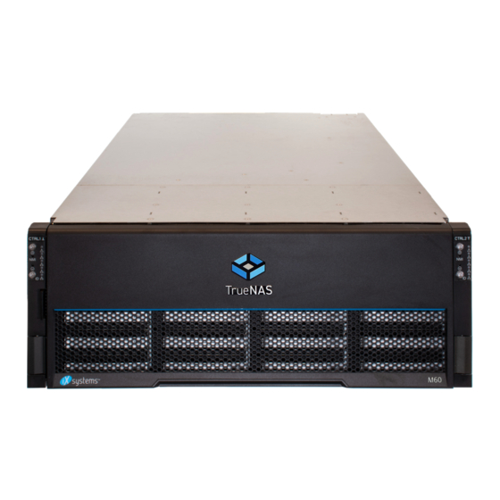
TrueNAS M Series Basic Setup Manual
Unified storage array
Hide thumbs
Also See for M Series:
- Basic setup manual (20 pages) ,
- Setup manual (16 pages) ,
- Setup manual (12 pages)
Table of Contents
Advertisement
Advertisement
Table of Contents

Subscribe to Our Youtube Channel
Related Manuals for TrueNAS M Series


Summary of Contents for TrueNAS M Series
- Page 1 TrueNAS M-Series Unified Storage Array ® Basic Setup Guide Version 3.1...
-
Page 2: Table Of Contents
.............. 7 TrueNAS Controller Installation and Removal ... -
Page 3: Become Familiar With The M-Series
1.1 Unified Chassis Design The 3rd Generation TrueNAS M-Series systems havea unified chassis design that allows systems to be upgraded with more powerful controllers. An M40 can be upgraded to an M50 or M60, and the M50 can be upgraded to an M60. -
Page 4: Front Panel Indicators
The front “ears” have indicators for power (1), locateID (2), fault (3), and network activity (4). The fault indicator is on during the initial power-on self-test (POST) and off during normal operation. It also turns on if the TrueNAS software issues an alert. -
Page 5: M-Series Expansion Slots
1.3 M-Series Expansion Slots Expansion slots on the M-Series are reserved for specific cards or internal use: Platform Slot * Slot A Slot B Slot C Slot D Slot E Slot F External SAS Internal SAS x4 NVMe Riser or Secondary NIC or Fibre Channel NIC1... -
Page 6: Prerequisites
2 Prerequisites There are a few considerations to make before handling or installing an M-Series system in a rack. 2.1 Handling The M-Series system weighs 75 lbs empty. Always team-lift the system! The total weight of a fully-populated system is over 110 lbs. -
Page 7: Series Rail Kit Assembly
3 M-Series Rail Kit Assembly At minimum, an M-Series requires 4U of space in a EIA-310 compliant rack that is 27” (686mm) deep, frame to frame. To properly install the rails, the vertical rack posts need to be spaced between 26” (660.4mm) and 36” (914.4mm) apart. -
Page 8: Mount The Unit In The Rack
Place the rail in the rack with the front end towards the front of the rack, aligning the pins with the mounting holes in the front of the rack. Push the pins into the holes until the latch clicks. At the rear end of the rail, align the pins with the rack holes, making sure the rail is level. Swing the gray latch handle outwards (1) and pull it to extend the rail rearwards until the rail pins are fully seated in the rack holes (2). -
Page 9: Install Drive Trays
4 Install Drive Trays TrueNAS appliances only support qualified hard drives and SSDs. Contact iXsystems Sales if you need more drives or replacements. Adding unqualified drives to the system voids the warranty. Call iXsystems Support if drives are improperly installed in trays. -
Page 10: Cabling
The Setup Guide included with an iXsystems Expansion Shelf has instructions for SAS connections. This example shows a typical M60 connection to a pair of iXsystems ES60 expansion shelves. Detailed connection diagrams are also available in the TrueNAS SAS Connections Guide. Page 8... -
Page 11: Network Cables
It is also recommended to connect network cables from the local switch or management network to the Out-of-Band (OOB) IPMI management port on each TrueNAS Controller. Refer to the network port labels in Section 1.2 as needed. Network ports are preconfigured to customer specifica- tions before shipment. -
Page 12: Install Bezel (Optional)
6 Install Bezel (Optional) The included bezel is not required for operation. To attach the bezel, slide the right side of the bezel into the attach- ment points on the right ear (1). Push the left side of the bezel into the left ear latch until it locks in place (2). To remove the bezel, push the left ear release tab away from the bezel to release. -
Page 13: Truenas Controller Installation And Removal
7 TrueNAS Controller Installation and Removal Warning: To avoid data loss in an NVDIMM SLOG, TrueNAS controllers must be properly shut down and powered off before they are removed from the chassis. 7.1 Adding a Second TrueNAS Controller M-Series systems with only one TrueNAS controller have an internal shipping brace that must be removed before adding a second TrueNAS controller. -
Page 14: Truenas Controller Installation
Press only on the bottom, sides, or handle of the TrueNAS controller, sliding it into the chassis until it stops (1). Lift the black release handle to lock the TrueNAS controller in place (2). Tighten the thumb screw to lock the handle. -
Page 15: Booting The System
8 Booting the System After plugging the power cords into outlets, the M_Series will power on and begin to boot into TrueNAS. The boot process can take some time. When booted, the system console displays the IP address of the TrueNAS M-Series graphical web interface, 192.168.100.231 in this example:... -
Page 16: Documentation
9 Documentation The TrueNAS Documentation Hub provides numerous articles designed to guide through configuring and using the software. It is available by clicking Guide in the TrueNAS web interface or going directly to https://www.truenas. com/docs/hub/. The TrueNAS Documentation Hub also provides an online version of this Guide and documentation of other iXsys- tems products at https://www.truenas.com/docs/hardware/.
Need help?
Do you have a question about the M Series and is the answer not in the manual?
Questions and answers