
Related Manuals for Element4 Kudos


Summary of Contents for Element4 Kudos
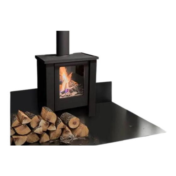
- Page 1 I N S TA L L AT I O N M A N U A L I N S TA L L AT I O N M A N U A L K U D O S Please leave these instructions behind with the device...
- Page 2 I N S T A L L A T I O N M A N U A L Do not use this product as a primary heat source...
-
Page 3: Table Of Contents
ELEMENT4 PROCONTROL APP� � � � � � � � � � � � � � � � � � � � � � � � � � � � � � � � � � � � � � �... - Page 4 I N S T A L L A T I O N M A N U A L DECORATIVE (CERAMIC) PARTS � � � � � � � � � � � � � � � � � � � � � � � � � � � � � � � � �16 10�1 DECORATION ARRANGEMENT �...
-
Page 5: Ce Statement
This declaration loses its validity when changes to the device are made Do not place any extra imitation logs or decoration material on without the written permission by Element4. You can ask for a copy of the burner or in the combustion chamber. See... -
Page 6: Warranty
In case the installer is not able to fix the problem himself, a request can be made to Element4 to do it for him, as long as the service can be done within the borders of the Benelux. -
Page 7: Remote Control With Full Electronic Ignition
REMOTE CONTROL WITH FULL ELECTRONIC IGNITION 4�2 IGNITING THE PILOT LIGHT Figure 4.1 The unit is operated using a remote control ( ) or the Element4 Figure 4.3 Check that the control knob (A) is in the ON position( ). Press Figure 4.2... -
Page 8: Installation Preparation And - Instruction
The flue system must be constructed from the appliance upwards, with needs no additional ventilation. However an adequate supply of all joints being fully locked and sealed using the Element4 specified fresh air to maintain temperatures and a comfortable environment is parts. -
Page 9: Fire Safe Installation
I N S T A L L A T I O N M A N U A L | Chapter 6 FIRE SAFE INSTALLATION To install a gas fireplace as safely as possible, several installation preparations need to be made. This overview can be used to assure the fire safety of a conversion of a fireplace. - Page 10 I N S T A L L A T I O N M A N U A L | Chapter 6 a’ Figure 6.1 | Distances to combustible materials (Top) Figure 6.1 | Distances to combustible materials (front) Letter Minimum Distance to flammable materials (mm) a - a’...
-
Page 11: Attention Points Flue Gas Extraction
(THS). In the table you will find advice; TVS on the vertical axis and THS on the Figure 7.1 | Restrictor positions of the Kudos horizontal axis. 7�1�2 CALCULATE FLUE LENGTH Not all parts can be adjusted! To fit the drainage system correctly, you are to use an adjustable fitting. -
Page 12: 7�2 Bends
For flue configurations that do not function on natural draft, the PowerFan can be used. For extensive installation instructions and the operation of the PowerFan we refer to the manual of the PowerFan on the Element4 website or via your dealer. -
Page 13: Electrical Circuit
The app has a user friendly, interactive layout and the design is adjusted Necessities for the installation of the ProControl: for Element4 devices. Up to eight devices can be used with one app, in • 220 volt electricty near the fire the situation that multiple fire are installed in the same location. -
Page 14: Maintenance Instruction
MAINTENANCE 9�4 CLEANING THE GLASS The Kudos fireplace is easy to maintain. The front of the fireplace can be Keep in mind the following when cleaning glass: completely removed for access to all parts in and under the fireplace. •... - Page 15 I N S T A L L A T I O N M A N U A L | Chapter 9 Figure 9.1 | Position of Allan nut Figure 9.3 | Gas control in brackets under fireplace Figure 9.5 | Removal of front frame Figure 9.2 | Front view after glass removal...
-
Page 16: 9�6 Servicing The Burner
9�6�3 THERMOCOUPLES The Element4 fireplaces have two thermocouples; one next to the pilot and one opposite the pilot side of the burner. The completeness and operation of both must be checked. A qualified installer must confirm that both thermocouples are in place and undamaged. -
Page 17: Decorative (Ceramic) Parts
DECORATION ARRANGEMENT and a vacuum cleaner. Where necessary replace damaged components only with genuine Element4 specified parts. Seal any scrap ceramics in Only the decoration ceramics supplied with this appliance are to be plastic bags and dispose at proper refuse sites. When using a vacuum used. -
Page 18: 10�2 Decoration Instructions
I N S T A L L A T I O N M A N U A L | Chapter 10 10�2 DECORATION INSTRUCTIONS Figure 10.4 Figure 10.2 Step 3: Step 1: Place the log burners in the designated openings in the grate. The picture on the right shows the empty burner grate. -
Page 19: Operating The Fireplace
I N S T A L L A T I O N M A N U A L | Chapter 11 OPERATING THE FIREPLACE 11�1 BEFORE THE FIRST FIRE Flames and soot During this first fire, examine the flame for appearance and quality. Make sure the cables of the ignition are hanging loosely under the Flames may appear blue at first, but will turn yellow after 15 to 20 device, to ensure a good ignition. -
Page 20: Atroubleshooter
I N S T A L L A T I O N M A N U A L | Appendix A TROUBLESHOOTER A�A FIRST AID FOR MALFUNCTION Below you will find an overview of the possible cause and solution in the event of a failure. - Page 21 I N S T A L L A T I O N M A N U A L | Appendix A 4,5 mV 4,5 mV Figure A.E | Figure A.A | Figure A.D | Interrupter Bend pin Testpoint Figure A.F | Figure A.B | Wiring receiver Antenna...
- Page 22 I N S T A L L A T I O N M A N U A L | Appendix A Problem Possible Cause Solution The pilot light goes Insufficient voltage across the thermocouple or Place the measuring pins of the multimeter on the ground and on but goes out too much resistance in the thermocouple circuit black cable of the breaker.
- Page 23 I N S T A L L A T I O N M A N U A L | Appendix A Figure A.H | Second thermocouple Figure A.L | “Double plus”-button on the remote Figure A.I | Button A on “On” Figure A.J | RESET-button Figure A.M |...
-
Page 24: A�Bnecessary Tools
If a problem is found, that cannot be solved on site, always contact your Element4 expects are being carried during said services. dealer or directly contact Element4 via our credentials which can be When all these tools are available during service, Element4 guarantees found on the back page of this manual. -
Page 25: Berrors Codes Procontrol App
I N S T A L L A T I O N M A N U A L | Appendix B ERRORS CODES PROCONTROL APP B�A MESSAGES SHOWN IN APP Error code Message in App Description Possible cause Contact Service. •... -
Page 26: B�Bmessages Shown In Remote
I N S T A L L A T I O N M A N U A L | Appendix B Error code Message in App Description Possible cause Contact Service. • It is not possible to increase flame height •... -
Page 27: Cfaults And Error Codes In The Remote
I N S T A L L A T I O N M A N U A L | Appendix C FAULTS AND ERROR CODES IN THE REMOTE Consult this appendix, when error messages occur in the application for smartphone and tablet. C�A F41 ERROR This message will appear if there is no or bad Wi-Fi reception, this can be... -
Page 28: Dterminal Location
I N S T A L L A T I O N M A N U A L | Appendix D TERMINAL LOCATION D�B TERMINAL LOCATION WITH HORIZONTAL EXHAUST (C31) D�A TERMINAL LOCATION WITH VERTICAL EXHAUST (C11) Distance Exhaust 1,2 of 3 Position terminal dist. -
Page 29: Ecalculation Tables Fluegas Restriction
I N S T A L L A T I O N M A N U A L | Appendix E CALCULATION TABLES FLUEGAS RESTRICTION Attention: For information on how to calcualte bends see CHAPTER 7 CHAPTER 7 In the calcualtion table yo ucan see when you need to place a flue gas restrictor This fireplaces has a minimal start length of 0.5 meter. -
Page 30: Ftechnical Data
I N S T A L L A T I O N M A N U A L | Appendix F TECHNICAL DATA The dataplate specifies for which type of gas, gas pressure and for which country this appliance is intended. The nameplate is attached to a chain. It must remain attached to the chain. -
Page 31: Gecodesign
The ecolabels for the different types of gas are indicated below, respectively G20, G25 and G30. From 2022 the UKCA label is used for the United Kingdom. Both versions may be found on your fireplace. ENERGY ENERGY Kudos Kudos | G30 | G20 2015/1186 Figure G.B |... -
Page 32: Hdimensional Drawings
On this page you will find trhr dimensional drawings of the fireplace with some of the important dimensions that you have to take into account when installing and installing your fireplace. 588,00 270,00 19,00 19,00 80,00 4,00 460,00 550,00 Figure H.A | Technical drawing of Kudos... - Page 33 Design & Assembly by: E L E M E N T 4 B . V. Info@element4.nl www.element4.nl 1 9 / 0 1 / 2 2 RELEASE DATE |...
Need help?
Do you have a question about the Kudos and is the answer not in the manual?
Questions and answers