Table of Contents
Advertisement
Quick Links
Advertisement
Table of Contents

Related Manuals for Create WIND FOLD


Summary of Contents for Create WIND FOLD
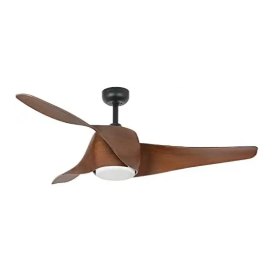
- Page 1 WIND FOLD CEILING FAN WITH LIGHT MANUAL ASSEMBLY ENGLISH...
- Page 4 W I ND FO LD To download this user guide in your language, visit our website: www.create-store.com/uk Para descargar el manual en su idioma, visite nuestra web: www.create-store.com/es Para baixar o manual no seu idiomas, visite nosso site: www.create-store.com/pt Pour télécharger le manuel dans votre langue, visitez notre site Web: www.create-store.com/fr...
-
Page 5: Table Of Contents
WIND FOLD INDEX Box c o n te n t s Step 1. Woo d roo f Step 1. C on c re te ce il ing Step 1. Fals e ce il ing C h oi c e o f grab b a r Step 2. -
Page 6: Box Contents
BOX CONTENTS FLOWER DRIVER REMOTE CONTROL LED PLATE EMBELLISHER ENGINE (x3) BLADES TULIPA SHANK EXTENSION POST MOUNTING BRACKET EMBELLISHER ENGINE (1) EXPANSION SCREWS TERMINALS SCREWS FOR TRIM + ENGINE SPLICE (2) WOOD SCREWS BALANCING KIT SUPPORT BLADE SCREWS BLADES ATTENTION! Before starting the as- sembly, remember to disconnect the light from the electrical panel so as not to suffer an electric shock. -
Page 7: Step 1. Wood Roof
STEP 1. WOOD ROOF PARTS AND TOOLS MATERIAL NOT INCLUDED (2) WOOD SCREWS OPTIONAL ACCORDING TO TYPE OF ROOF SUPPORT OF MOUNTING Mark with a pencil the 4 holes of the piece If necessary, depending on the type of K in the roof. roof, you will need to use a drill to make the hole in the wood. -
Page 8: Step 1. Concrete Ceiling
STEP 1. CONCRETE CEILING PARTS AND TOOLS MATERIAL NOT INCLUDED (1) EXPANSION SCREWS SUPPORT OF MOUNTING disassemble the part M separating it into pieces. Ø8mm Mark with a pencil the 2 central holes of With the help of a drill, make the two cor- the piece K on the ceiling using the same responding holes with a Ø8 mm drill bit. - Page 9 place the piece K matching their holes Enter the part in order M2, M3 and then with the screws M1. Make sure the ceiling the nut M4. cables are on one side of the piece K. Tighten the part M4 with a No. 10 wrench, Make sure the part K It is perfectly hooked until you feel it's ok to the ceiling and...
-
Page 10: Step 1. False Ceiling
STEP 1. FALSE CEILING PARTS AND TOOLS MATERIAL NOT INCLUDED FIXING SCREWS WITH SPRING LEVER SUPPORT OF MOUNTING Mark the 2 central holes of the piece on With the help of a drill, make the 2 corre- the ceiling with a pencil K using the same sponding holes. -
Page 11: Choice Of Grab Bar
CHOICE OF GRAB BAR Before you start, choose the desired height. (10cm+/-) You will have to choose between the height of the piece I wave J. · If you choose the height of the piece J, You must follow the instructions below. ·... - Page 12 Snap the tilt bracket onto Tighten the two screws on Put the pin back in the piece the pin. the tilt bracket with the screwdriver. Secure the pin with the The piece is already J ready locking piece so that it does to use.
-
Page 13: Step 2. Blade Assembly
STEP 2. BLADE ASSEMBLY (x7) SCREWS BLADE SUPPORT (x3) ENGINE BLADES BLADES Start by removing the engine bolts. H, if your screws Q are in a plastic bag, go to step 4. Remove the blade support bolts. R and save them for the next step. Start placing the blades E screwing the screws Q from the bottom of the engine H, as shown in the images. - Page 14 Once the first blade is located E and fasten the screws Q to the engine H, rotate the center piece so that the driver cables are facing up. Place the blade support R on top of engine H and below the blades E. tighten the blade E with the screws you removed from the blade holder R.
-
Page 15: Step 3. A S S E Mb Ly Of The Mai N B Ody 1
STEP 3. ASSEMBLY OF THE MAIN BODY EMBELLISHER FLOWER ENGINE CHOOSE THE HEIGHT YOU NEED ENGINE Remove the pin from the Insert the seatpost I/J, through the hole in the part A. part I/J, depending on the chosen height. Insert the seatpost I/J, Once the piece is inserted through the hole in the part A Y L, you must insert the... -
Page 16: Step 4. Driver Connection
With the help of a screw- Insert the seatpost into the Once the seatpost has been driver, remove the 2 screws top of the piece H. Make inserted, place the pin of the from the top of the piece H. sure no wires get pinched. - Page 17 Remember to set the notch Put the tilt bracket into the Before continuing, check on the tilt bracket back so slot on the part K. that the central structure is that the piece fits snugly. well placed so that it does not fall.
- Page 18 Connect the L cable of the Connect the N wire of the Make sure everything is at- driver to the PHASE cable driver to the NEUTRAL wire tached correctly. of your installation. of your installation. slide piece A upwards to fit it on the protruding screws of Once fitted, turn the piece the piece K.
-
Page 19: Step 5. Fitting The Trim
STEP 5. FITTING THE TRIM SCREWS FOR EMBELLISHER EMBELLISHER Using a screwdriver, remove the 3 center screws from the Pass the fan cables through motor for later use. If these screws come in a sealed bag, the center hole of the piece use them for this step. -
Page 20: Step 6. Led Board Connection
STEP 6. LED BOARD CONNECTION LED PLATE Connect the part wires D to those of the fan joining the connections, each cable with its same color. Then attach the part D to the fan with the help of the magnets so that it stays in place. ENGLISH... -
Page 21: Step 7. Placement Of La Tulipa
STEP 7. PLACEMENT OF LA TULIPA TULIPA place the piece F on the fan by fitting it into the trim and turn it clockwise. Do not forget to check that the piece is well secured. Once checked, you can connect the electricity and enjoy your new fan with light. -
Page 22: Blade Balancing Kit
BLADE BALANCING KIT BALANCING KIT Your ceiling fan may have swinging problems when operating due to irregularities in the blades or brackets. In addition, incorrect mounting of the system or twisted bearings could cause additional problems. The following procedure is recommended to remedy these prob- lems: 1. - Page 24 ENGLISH...
Need help?
Do you have a question about the WIND FOLD and is the answer not in the manual?
Questions and answers