Table of Contents
Advertisement
Quick Links
Advertisement
Table of Contents

Related Manuals for Create Wind Flat


Summary of Contents for Create Wind Flat
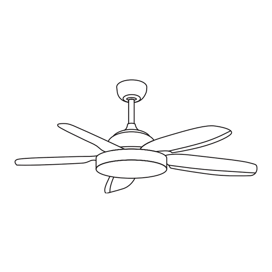
- Page 1 Wind Flat Aseembly manual...
- Page 4 To download this user guide in your language, visit our website: www.create-store.com/uk Para descargar el manual en su idioma, visite nuestra web: www.create-store.com/es Para baixar o manual no seu idiomas, visite nosso site: www.create-store.com/pt Pour télécharger le manuel dans votre langue, visitez notre site Web: www.create-store.com/fr...
-
Page 5: Table Of Contents
INDE X Box c o n te n t Step 1. Woo d cei li ng Step 1. C on c re te ce il ing Step 1. Fals e ce il ing Step 2. Mai n b od y as se mb ly Step 3. -
Page 6: Box C O N Te N T
BOX CONTENT CANOPY DRIVER FOR LED LED PLATE DRIVER (x5) BLADES LAMP COVER DECORATIVE ELEMENT BRACKET + MOTOR SMALL DOWNROD EXTENSION BAR REMOTE CONTROL MOUNTING BRACKET DECORATIVE ELEMENT OF MOTOR (1) EXPANSION SCREWS SCREWS FOR DECORATIVE COVER COVER BALANCING KIT ELEMENT + MOTOR SCREW COUPLING... -
Page 7: Step 1. Wood Ceiling
STEP 1. WOOD CEILING PARTS AND TOOLS NOT INCLUDED (2) WOOD SCREWS OPTIONAL ACCORDING TO CEILING TYPE Mark on the ceiling with a pencil the 4 If necessary, depending on the type of holes of piece L. ceiling, you will need to use a drill to make the hole in the wood. -
Page 8: Step 1. Concrete Ceiling
STEP 1. CONCRETE CEILING PARTS AND TOOLS NOT INCLUDED (1) EXPANSION SCREWS Disassemble part N separating it into pieces. Ø8 mm Mark on the ceiling with a pencil the 2 cen- With the help of a drill, make the two cor- tral holes of piece l, using the same piece responding holes with an Ø8 mm drill bit. - Page 9 Place part L matching its holes with the Insert pieces N2, N3 and subsequently the screws N1. Make sure the ceiling wires are nut N4. placed on one side of piece L. Tighten piece N4 with a # 10 wrench, until Make sure that piece L is perfectly hooked you feel that it is well fixed.
-
Page 10: Step 1. False Ceiling
STEP 1. FALSE CEILING PARTS AND TOOLS NOT INCLUDED FIXING SCREWS WITH SPRING LEVER Mark on the ceiling with a pencil the 2 cen- With the help of a drill, make the two cor- tral holes using piece L as a guide. responding holes. -
Page 11: Step 2. Main Body Assembly
STEP 2. MAIN BODY ASSEMBLY CHOOSE THE HEIGHT YOU NEED Remove the pin from part I. Insert the bar through the hole in part A. Insert part M as shown in Once the pieces A and M are inserted, you must insert the the picture. - Page 12 With the help of a screwdriv- Insert the bar at the top of Make sure no wires are er, remove the 2 screws at piece H. pinched. the top of piece H. Once the bar is inserted, Place the locking piece on Then replace place the pin of piece I so...
-
Page 13: Step 3. Driver Connection
STEP 3. DRIVER CONNECTION DRIVER WIRE CONNECTORS Remember to put the notch of the black top of the tilt support Place the tilt support in the backwards so that the piece fits properly. slot of piece L. Before continuing, check Once the wires are connec- Select and connect all the that the center frame is... - Page 14 Once connected, place Then, you have to join the re- Connect the L wire from the piece P screwing it until it maining wires of piece B and driver with the LINE wire is well tighten. the line and neutral wires from your house wiring.
-
Page 15: Step 4. Assembling The Blades
Finally, with the help of a screwdriver, tighten the screws so that the piece is well fixed. STEP 4. ASSEMBLING THE BLADES (x5) BLADES Remove the 15 screws from the bottom of piece H to be used later in the assembly of the blades. -
Page 16: Step 5. Pla Ci Ng T He De Co Rat I Ve El Eme
Repeat the step with the 4 remaining blades making sure that they are perfectly attached. STEP 5. PLACING THE DECORATIVE ELEMENT With a screwdriver remove the 3 central screws of the motor Pass motor wires to use them later. through the center hole of piece G. -
Page 17: Option With Led Kit
Place piece G aligning its Firmly tighten the screws removed in step 1 so that piece G holes with the holes in the is properly attached. motor. OPTION WITH LED KIT STEP 6. LED PLATE CONNECTION DRIVER FOR LED LED PLATE Connect the wires of the driver C with those of the LED plate Once connected, place the D by joining the connectors. -
Page 18: Step 7. Pl Ac I Ng T He La Mp Cover 1
Next, place the driver on piece G where the magnets are without covering any LEDs. STEP 7. PLACING THE LAMP COVER LAMP COVER Place piece F on piece G until it fits correctly, as shown in the image. Please make sure that piece F is securely fastened. -
Page 19: Option Without Led Kit
OPTION WITHOUT LED KIT STEP 8. FITTING THE COVER COVER COVER COVER COUPLING SCREW Carefully insert the fan wires inside piece S and take them out through the large side hole of this piece. Then screw piece S and check that it remains securely attached to the fan. Take piece Q and tighten the screw R into the hole so that it is securely attached. - Page 20 Then take the piece Q and tighten the screw R on the nut S previously placed on the fan. Once the piece is in place, you can connect the electricity and enjoy your new fan. ENGLISH...
-
Page 21: Blade Balancing Kit
BLADE BALANCING KIT Your ceiling fan may have blade swing problems when in operation due to irregularities in the blades or brackets. Also, incorrect system mounting or crooked bearings could cause additional problems. The following procedure is recommended to remedy these problems: 1. - Page 24 ENGLISH...
Need help?
Do you have a question about the Wind Flat and is the answer not in the manual?
Questions and answers