Table of Contents
Advertisement
Quick Links
Advertisement
Table of Contents

Subscribe to Our Youtube Channel
Related Manuals for Create WIND MINIMAL


Summary of Contents for Create WIND MINIMAL
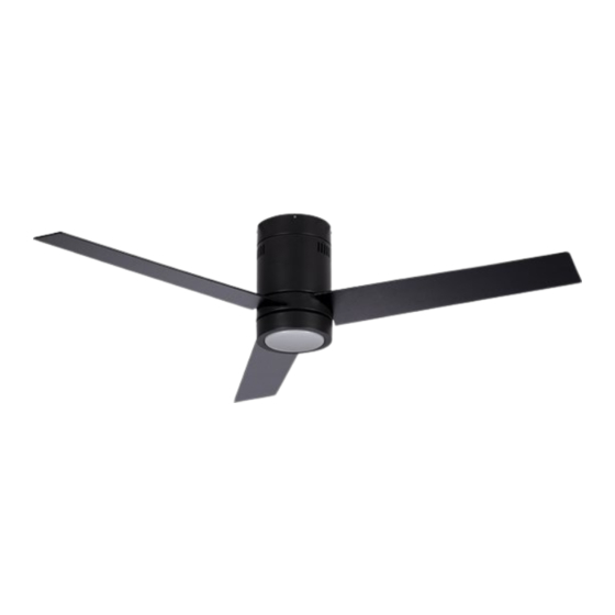
- Page 1 WIND MINIMAL CEILING FAN WITH LIGHT MANUAL ASSEMBLY ENGLISH...
- Page 4 W I ND MINIMA L To download this user guide in your language, visit our website: www.create-store.com/uk Para descargar el manual en su idioma, visite nuestra web: www.create-store.com/es Para baixar o manual no seu idiomas, visite nosso site: www.create-store.com/pt Pour télécharger le manuel dans votre langue, visitez notre site Web: www.create-store.com/fr...
-
Page 5: Table Of Contents
WIND MINIMAL INDEX Box c o n te n t s Step 1. Woo d roo f Step 1. C on c re te ce il ing Step 1. Fals e ce il ing Step 2. D ri ver c o nnec ti on Step 3. -
Page 6: Box Contents
BOX CONTENTS DRIVER REMOTE CONTROL LED PLATE (x3) BLADES MOUNTING SUPPORT EMBELLISHER ENGINE TULIPA (1) EXPANSION SCREWS (2) WOOD SCREWS SCREWS FOR BALANCING KIT TRIM + ENGINE SPLICING TERMINALS BASE SCREWS + MOTOR BLADE SCREWS ATTENTION! Before starting the as- sembly, remember to disconnect the light from the electrical panel so as not to suffer an electric shock. -
Page 7: Step 1. Wood Roof
STEP 1. WOOD ROOF PARTS AND TOOLS MATERIAL NOT INCLUDED (2) WOOD SCREWS OPTIONAL ACCORDING TO TYPE OF MOUNTING BRACKET ROOF Mark with a pencil the 4 holes of piece H If necessary, depending on the type of on the ceiling. ceiling, you will need to use a drill to make the holes in the wood. -
Page 8: Step 1. Concrete Ceiling
STEP 1. CONCRETE CEILING PARTS AND TOOLS MATERIAL NOT INCLUDED (1) EXPANSION SCREWS MOUNTING BRACKET I(1) I(2) I(3) I(4) Disassemble the part I separating it into pieces. Ø8 mm Mark 2 parallel holes on the ceiling with a Using a drill, make the two corresponding pencil using piece H as a guide. - Page 9 Insert piece I2, I3 and the nut I4 following Tighten piece I4 with a number 10 wrench, this order. until they are well fixed. Make sure that piece H is perfectly hooked to the ceiling. ENGLISH...
-
Page 10: Step 1. False Ceiling
STEP 1. FALSE CEILING PARTS AND TOOLS MATERIAL NOT INCLUDED FIXING SCREWS WITH SPRING LEVER MOUNTING BRACKET Mark 2 parallel holes on the ceiling with a With the help of a drill, make the two cor- pencil using piece H as a guide. responding holes. -
Page 11: Step 2. Driver Connection
STEP 2. DRIVER CONNECTION PARTS AND TOOLS DRIVER ENGINE SPLICING TERMINALS Insert the piece hook H in a hole in the piece G so that the motor hangs and facilitates the connection of the cables. Join the part connections G with those of the piece A, each with its corresponding color. - Page 12 Insert the piece A inside the Select and connect all the Once connected, place the piece G, As shown in the pic- ground cables, including the part L screwing it on until it ture. one for your installation. is secure. Connect the PHASE cable Connect the NEUTRAL ca- Once connected, place the...
-
Page 13: Step 3. Anchor The Motor To The Ceiling
STEP 3. ANCHOR THE MOTOR TO THE CEILING BASE SCREWS + MOTOR use 2 screws M and screw them, without tightening them take out the piece G of the too much, into the parallel holes of the piece H. hook and fit it on the piece H without pinching any wires. -
Page 14: Step 4. Blade Assembly
STEP 4. BLADE ASSEMBLY SCREWS OF BLADES BLADES If the screws N go in a plastic bag, go straight to step 4. If not, remove all screws N. Place the first blade D fastening it with the screws N and with the help of the screwdriver, without tightening them too much. -
Page 15: Step 5. Fi Tti N G T He T Rim 1
STEP 5. FITTING THE TRIM SCREWS FOR EMBELLISHER EMBELLISHER Using a screwdriver, remove the 3 center screws from the Pass the fan cables through motor for later use. If these screws come in a sealed bag, the center hole of the piece use them for this step. -
Page 16: Step 6. Led Board Connection
STEP 6. LED BOARD CONNECTION LED PLATE Connect the part wires C to those of the fan joining the connections, each cable with its same color. Then attach the part C to the fan with the help of the magnets so that it stays in place. ENGLISH... -
Page 17: Step 7. Pl Ac Em Ent Of T He La Mp S Ha
STEP 7. PLACEMENT OF THE LAMPSHADE TULIPA Place the piece E on the fan fitting it into the trim and turn it clockwise. Do not forget to check that the piece is well secured. Once checked, you can connect the electricity and enjoy your new fan with light. -
Page 18: Blade Balancing Kit
BLADE BALANCING KIT BALANCING KIT Your ceiling fan may have swinging problems when operating due to irregularities in the blades or brackets. In addition, incorrect mounting of the system or twisted bearings could cause additional problems. The following procedure is recommended to remedy these prob- lems: 1. - Page 20 ENGLISH...
Need help?
Do you have a question about the WIND MINIMAL and is the answer not in the manual?
Questions and answers