Table of Contents
Advertisement
Quick Links
Advertisement
Table of Contents

Related Manuals for Blue-White FLEXFLO A2 Series


Summary of Contents for Blue-White FLEXFLO A2 Series
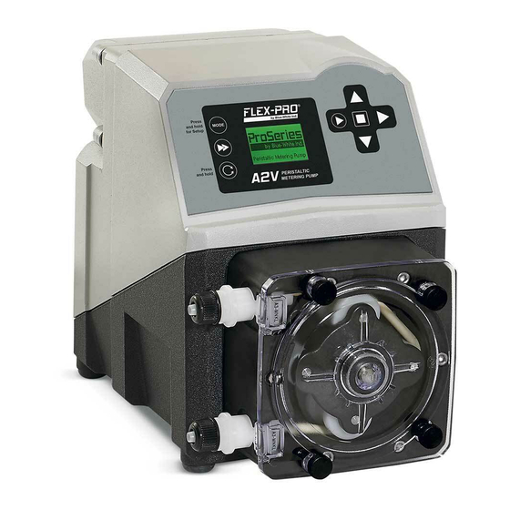
- Page 1 ® FLEXFLO Peristaltic Metering Pump Series A2...
-
Page 2: Table Of Contents
® FLEXFLO A2 Introduction Available Models Specifications Materials of Construction Features Agency Listings Installation Mounting Location Dimensions Installing Injection Fitting and Strainer Power Connections A2F Wiring Terminal and I/O Schematics A2V Wiring Terminal and I/O Schematics How to Operate Flex-Pro - Control Pad A2F Touch Pad Layout A2V Touch Pad Layout 6.3 Mode Descriptions... - Page 3 ® FLEXFLO A2 Page 3 READ THE INSTRUCTION MANUAL PRIOR TO INSTALLATION AND USE. +1 (714) 893 - 8529 sales@blue-white.com customerservice@blue-white.com 5300 Business Drive Huntington Beach, CA 92649...
-
Page 4: Introduction
Please Note: Your new pump has been pressure tested at factory with clean water before shipping. You may notice trace amounts of clean water in pre-installed tube assembly. This is part of our stringent quality assurance program at Blue-White Industries. Available Models Optional Extended Brackets Stainless Steel extended brackets allow pump to be securely mounted to most any surface;... -
Page 5: Specifications
® Page 5 FLEXFLO A2 Specifications Maximum Working Pressure 125 psig (8.6 bar) Maximum Fluid Temperature 185 °F (85 °C) Maximum Ambient Temperature 14 °F to 115 °F/ -10 °C to 46 °C Maximum Viscosity 12,000 Centipoise Maximum Suction Lift 30 ft. -
Page 6: Materials Of Construction
® Page 6 FLEXFLO A2 Materials of Construction Non-wetted Components: Wetted Components: Enclosure: Pump Tube Assembly: 413 Aluminum (Polyester powder coated) Pump Head: ® Tubing : Flex-A-Prene ® , Flex-A-Chem ® or Flex-A-Thane ® Valox (PBT) thermoplastic Pump Head Cover: Polycarbonate Adapter Fittings : PVDF Injection/Back-Flow Check Valve:... -
Page 7: Features
Heavy duty rotor - single piece plastic rotor means no flexing and increased accuracy with no metal springs or hinges to corrode. Inject at maximum pressure in either direction (clockwise and counter clockwise). Compatible with Blue-White’s output Flow Verification Sensor (FVS) system. Agency Listings This pump is ETL listed to conforms to the following: UL Standard 778 as a motor operated water pump CSA Standard C22.2 as process control equipment... -
Page 8: Installation
® Page 8 FLEXFLO A2 Installation CAUTION Risk of chemical overdose. Be certain pump does not overdose chemical during backwash and periods of no flow in circulation system. CAUTION Always wear protective clothing, face shield, safety glasses and gloves when working on or near your metering pump. -
Page 9: Installing Injection Fitting And Strainer
® Page 9 FLEXFLO A2 Installing Injection Fitting and Strainer CAUTION Proper eye and skin protection must be worn when installing and servicing pump. CAUTION This Pump Has Been Evaluated for Use with Water Only. Injection Fitting and Strainer for ½” (1.3cm) I.D. Connection End Models Discharge Injection Fitting / Check Valve) Suction Strainer Pipe... -
Page 10: Power Connections
® Page 10 FLEXFLO A2 Power Connections WARNING Risk of electric shock – cord connected models are supplied with a grounding conductor and grounding-type attachment plug. To reduce risk of electric shock, be certain that it is connected only to a properly grounded, grounding-type receptacle. WARNING Electrical connections and grounding (earthing) must conform to local wiring codes. -
Page 11: A2F Wiring Terminal And I/O Schematics
300V minimum. FUNCTION BLOCK DIAGRAM TERM PIN # RATING ELECTRICAL SP. INPUT: (+) POSITIVE PWR (+) RED (+) FVS SYSTEM BLUE-WHITE SIGNAL (FLOW VERIFICATION FVS SENSOR BARE SIGNAL GND (-) SENSOR) FV SENSOR ONLY BLACK (-) (-) NEGATIVE INPUT:... -
Page 12: A2V Wiring Terminal And I/O Schematics
GND (-) FREQUENCY, AC SOURCE SINE WAVE, TTL, PULSE CMOS (+) POSITIVE INPUT: (+) POSITIVE PWR (+) RED (+) FVS SYSTEM BLUE-WHITE SIGNAL (FLOW VERIFICATION FVS SENSOR BARE SIGNAL GND (-) SENSOR) FV SENSOR ONLY BLACK (-) (-) NEGATIVE INPUT:... -
Page 13: How To Operate Flex-Pro - Control Pad
® Page 13 FLEXFLO A2 How to Operate the Flex-Pro - Control Pad A2F Touch Pad Layout Press and release To prime pump (60 seconds) ® Press and hold To change rotor direction clockwise or counterclockwise Press and Hold Press and release To configure selected Mode Press UP arrow to increase Remote Start / Stop... -
Page 14: A2V Touch Pad Layout
® Page 14 FLEXFLO A2 A2V Touch Pad Layout Press and release To select Run Mode Mode 1: Manual Mode 2: 4-20mA input Mode 3: Frequency input ® Mode 4: Pulse / Batch Press and Hold To configure selected Mode Mode 0: Setup Mode 1: Manual Mode 2: 4-20mA input... -
Page 15: Mode Descriptions
® Page 15 FLEXFLO A2 Mode Descriptions Mode 0 Press and Hold to configure: Remote Start / Stop Ÿ TFD (Tube Failure Detection) sensitivity Ÿ FVS (Flow Verification Sensor) time delay - requires sensor Ÿ 4-20 mA output, available on certain models Ÿ... -
Page 16: Mode0 - Set Remote Start/Stop
® Page 16 FLEXFLO A2 Mode 0 - Set Remote Start / Stop Used to remotely start and stop pump using a dry contact closure signal. When activated; CLOSE = START and OPEN = STOP. Set to NO = Remote Start / Stop is disabled Set to Yes = Remote Start / Stop is enabled Can be used with external foot pedal, PLC, contact closure or other similar external devices. -
Page 17: Mode 0 - Set Tfd Sensitivity
® Page 17 FLEXFLO A2 Mode 0 - Set TFD Sensitivity Flex-Pro pump is equipped with a Tube Failure Detection (TFD) system which is designed to stop pump in event pump tube should rupture and chemical enters pump head. This patented system is capable of detection pres- ence of a large number of chemicals including Sodium Hypochlorite (chlorine), Hydrochloric (muriatic) Acid, Sodium Hydroxide, and many others. -
Page 18: Mode 0 - Set Fvs (Flow Verification System)
® Page 18 FLEXFLO A2 Mode 0 - Set FVS (flow verification system) Flow verification sensor sold separately. Flow verification system is designed to stop pump in an event sensor does not detect flow during pump operation. Indicating an empty chemical tank, clogged injection fitting, loose tubing connection, etc. To allow pump to clear any gasses that may have accumulated over time, an alarm delay time value from 1 to 255 seconds must be programmed. - Page 19 ® Page 19 FLEXFLO A2 Mode 0 - Set FVS (flow verification system) - Continued Flow Verification Sensor is designed to give you two installation options. Sensor can be installed: Directly on pumphead of A2 pump, suction side. Anywhere on suction side of A2 pump. Wiring for sensor can be connected directly to an A2 pump.
-
Page 20: Mode 0 - Set 4-20Ma Output
® Page 20 FLEXFLO A2 Mode 0 - Set 4-20mA Output Available on certain models. Sends a configurable 4-20 mA signal, based on pump rotor speed, to an external device. This feature can be used to control other pumps (in sync / proportionally), data logging systems, and other external devices for plant automation. - Page 21 ® Page 21 FLEXFLO A2 Mode 0 - Set 4-20mA Output - Continued 4-20 mA Icon Step 5 Output signal at minimum speed will now be displayed. To increase value, press and release UP arrow. To decrease value, press and release DOWN arrow. To save value, press and release RIGHT arrow.
-
Page 22: Mode 1 - Manual Operation
® Page 22 FLEXFLO A2 Mode 1 - Manual Operation Used to manually control speed of pump. Use UP and DOWN arrows to adjust speed while pump is running. To select exact run speed, follow steps below. Step 1 Mode 1 Press and release STOP button SPEED Note: Mode cannot be changed while pump is in running. -
Page 23: Mode 1 - Manual Operation Screen Shots
® Page 23 FLEXFLO A2 Mode 1 - Manual Operation Screen Shots Runtime Screen Shot 1 Display motor speed percentage. 35.0 SPEED Pump Running in Manual Operation Runtime Screen Shot 2 Display 4-20mA output (select models only) Press and release RIGHT arrow to view mA output value in real-time. -
Page 24: Mode 2 - 4-20Ma Input Operation (A2V Pump Only)
® Page 24 FLEXFLO A2 Mode 2 - 4-20mA Input Operation (A2V Pump Only) Default Setting Used to remotely control pump with an incoming 4-20 mA signal. Default setting: 4 mA signal = 0.1% motor speed 20 mA signal = 100.0% motor speed 8 10 12 14 16 18 20 Milliamp Output (mA) Signal Step 1... -
Page 25: Mode 2 - 4-20Ma Input Screen Shots
® Page 25 FLEXFLO A2 Mode 2 - 4-20mA Input Operation (A2V Pump Only) - Continued Step 6 Mode 2 mA value linked to maximum pump speed will now be displayed. To increase value, press and release UP arrow. To decrease value, press and release DOWN arrow. To save value, press and release RIGHT arrow. -
Page 26: Mode 3 - Frequency Input (Hz) Operation (A2V Pump Only)
® Page 26 FLEXFLO A2 10.0 Mode 3 - Frequency Input (Hz) Operation (A2V Pump Only) Used to remotely control pump with an incoming high speed frequency signal. Typically used with flow meters or other external devices. Default Setting Default setting: 0 Frequency (Hz) = 0% motor speed 100% 1000 Frequency (Hz) = 100% motor speed Output... - Page 27 Example #2, Paddlewheel flow meter Paddlewheel Injection Injection Flow Sensor / Meter Point Point S3 Series | Hybrid Ultrasonic Flowmeter NEMA 4X IP 66 Ultrasonic Flow Meter Doppler / ProSeries Transit Time by Blue-White Ind. Industries, Ltd. Discharge Line Discharge Line...
-
Page 28: Mode 4 - Pulse Batch (Low Speed Pulse) Operation (A2V Pump Only)
® Page 28 FLEXFLO A2 11.0 Mode 4 - Pulse Batch (low speed pulse) Operation (A2V Pump Only) Used to remotely control pump with an incoming pulse signal. Can be used with an external foot pedal, a water meter, a PLC, contact closure, or other low speed pulse devices. Default Setting Default setting: 1 Pulse = 100% motor speed for 2.5 seconds 100%... -
Page 29: Mode 4 - Pulse Batch Operation Screen Shots
® Page 29 FLEXFLO A2 11.0 Mode 4 - Pulse Batch (low speed pulse) Operation (A2V Pump Only) - Continued Mode 4 Step 5 Number of pulses to trigger pump start will be displayed. To increase value, press and release UP arrow. To decrease value, press and release DOWN arrow. -
Page 30: Pump Tube Timer
® Page 30 FLEXFLO A2 12.0 Pump Tube Timer Flex-Pro has a built in Pump Tube Timer. Timer starts when rotor is rotating and stops when rotor is idle. To view current Pump Tube Timer value, press and hold START button, then press and release DOWN arrow. Tube Timer screen will appear. -
Page 31: Alarm Relay
® Page 31 FLEXFLO A2 14.0 Alarm Relay Pump has a built in 3 amp alarm output relay. Relay is pre-configured to energize on tube failure detection (TFD) and on Flow Verification Sensor (FVS). A Flow Verification Sensor must be installed and configured for relay to trigger on no-flow conditions. 15.0 Reverse Rotor Rotation CAUTION... -
Page 32: Tube Replacement
® Page 32 FLEXFLO A2 16.0 Tube Replacement CAUTION Prior to service, pump clean water through pump and suction / discharge line to remove chemical. Always wear protective clothing, face shield, safety glasses and gloves when working on or CAUTION near your metering pump. -
Page 33: Tube Installation
® Page 33 FLEXFLO A2 16.2 Tube Installation Before you begin. Thoroughly clean Pump Head and Rotor. Rotor can be removed by pulling straight out. After cleaning process, push Rotor back on shaft. See drawing below for proper assembly. IMPORTANT! Rotor direction;... -
Page 34: Pump Maintenance
® Page 34 FLEXFLO A2 17.0 Pump Maintenance CAUTION Always wear protective clothing, face shield, safety glasses and gloves when working on or near your metering pump. Additional precautions should be taken depending on solution being pumped. Refer to MSDS precautions from your solution supplier. Routine Inspection and Maintenance Pump requires very little maintenance. -
Page 35: Output Versus Fluid Viscosity
® Page 35 FLEXFLO A2 18.0 Output Versus Fluid Viscosity Flow Rate (ml/min) Flow Rate (ml/min) Flow Rate (ml/min) Flow Rate (ml/min) -
Page 36: A2 Replacement Parts List
® Page 36 FLEXFLO A2 19.0 A2 Replacement Parts List Pump Head Components Spacer 90011-217 $1.42 Complete Roller Assembly $570.67 A2-SND-R NEE / NGG A2-SNGG-R A2-STH-R GE / GG A2-SGE-R Tubing (Reference Tubing Matrix) Pump Head Cover A2-SXX-C $200.78 *Pump Head not for sale. For more information please contact a local sales representative. -
Page 37: Tube Matrix
® Page 37 FLEXFLO A2 19.1 Tube Matrix Tubing Inlet/Outlet Connection Size, Connection Type, Connection Material 3/8” OD x 1/4” ID Tube Compression Fitting, Natural PVDF (Kynar) 1/2” Male NPT Fitting, Natural PVDF (Kynar) 1/2” Hose Barb, Natural PVDF (Kynar), available for ND, NEE, NGG, and G2G only 1/2”... -
Page 38: Warranty
Blue-White does not have the same degree of familiarity with the application that the customer/end user has. While Blue-White will honor all of its product warranties according to their terms and conditions, Blue- White shall only be obligated to repair or replace its defective parts or products in accordance with the associated product warranties. -
Page 39: Model Number Matrix
® Page 39 FLEXFLO A2 21.0 Model Number Matrix FLEXFLO ® Peristaltic Metering Pump Series Control Options Single manual output control (manual/local control only) Multiple automatic input output control and alarm modes (remote control) Power Cord (operating voltage requirement 96VAC to 264VAC) 115V / 60Hz, power cord NEMA 5/15 plug (US) 240V / 50HZ, power cord AS 3112 plug (AU/New Zealand) 230V / 60Hz, power cord NEMA 6/15 plug (US) - Page 40 The WEEE marking applies only to countries within the European Union (EU) and Norway. Appliances are labeled in accordance with European Directive 2002/96/EC. Contact your local waste recovery agency for a Designated Collection Facility in your area. www.blue-white.com sales@blue-white.com customerservice@blue-white.com P.N.
Need help?
Do you have a question about the FLEXFLO A2 Series and is the answer not in the manual?
Questions and answers
pump stops after a few seconds and says cvr on the screen