
Related Manuals for SystemAir Geniox GO


Summary of Contents for SystemAir Geniox GO
- Page 1 Geniox GO Air handling unit User Manual Document in original language | Version v7.2 Part number of this manual 211728...
- Page 2 211728 | v7.2...
- Page 3 12 Report with data from final functional test on the Systemair factory 13 Short description of main components in the control system 14 Wiring diagram (in separate cover) 15 Operator’s guide (How to use the Systemair control panel) (in separate cover) 211728 | v7.2...
-
Page 5: Table Of Contents
Lock the doors by using the key..................21 Installation - electrical ......................22 J.2.1 Installation of cable sealing boxes (only in rotor sections of Geniox GO 27—31) ....... 22 Installation – Pipes for water – hot and chilled, valves and drains ............22 J.3.1 Description....................... - Page 6 Contents M.1.2 Common for all unit sections ..................28 M.1.3 Common for all unit sections by insufficient lighting ............29 M.1.4 Dampers........................29 M.1.5 Attenuators......................29 M.1.6 Filters ........................29 M.1.7 Plug fans ......................... 30 M.1.8 Batteries for heating and cooling................... 30 M.1.9 Heat pump units......................
- Page 7 Indication of operation mode via red and green LED as well as test of motor......75 7.2.3 Copy of the label with information about connection of cables..........76 Assemble of split rotor for Geniox GO 27, Geniox GO 29 and Geniox GO 31 ........77 7.3.1 Dimensions of split rotor sections .................. 77 7.3.2...
-
Page 9: A Manufacturer
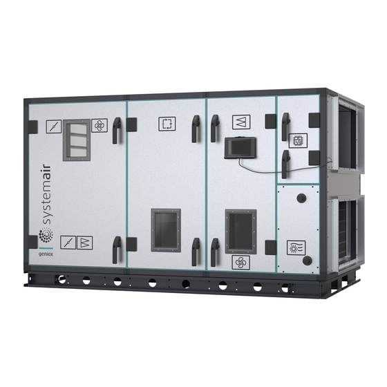
This manual is about Systemair air handling units called Geniox GO 10, Geniox GO 11, Geniox GO 12, Geniox GO 14, Geniox GO 16, Geniox GO 18, Geniox GO 20, Geniox GO 22, Geniox GO 24, Geniox GO 27, Geniox GO 29, and Geniox GO... -
Page 10: C Declaration Of Conformity
DXRDR/DXRDL, Geniox GO 16-RDR/RDL/XDR/XDL/RADR/RADL/CXDR/CXDL/DXRDR/DXRDL, Geniox GO 18-RDR/RDL/XDR/XDL/RADR/RADL/CXDR/ CXDL/DXRDR/DXRDL, Geniox GO 20-RDR/RDL/XDR/XDL/RADR/RADL/CXDR/CXDL/DXRDR/DXRDL, Geniox GO 22-RDR/RDL/XDR/XDL/RADR/RADL/ DXRDR/DXRDL, Geniox GO 24-RDR/RDL/XDR/XDL/RADR/RADL/DXRDR/DXRDL, Geniox GO 27.13-RSR/RSL/XSR/XSL/RASR/RASL, Geniox GO 29.14- RSR/RSL/RASR/RASL, Geniox GO 31.15-RSR/RSL/RASR/RASL. (The declaration applies only to product in the condition it was delivered in and installed in the facility in accordance with the included installation instructions. -
Page 11: D General Descriptions, Dangers And Warnings
General descriptions, dangers and warnings | General descriptions, dangers and warnings Geniox GO air handling units are order specific machines available in many different configurations. Only a few exam- ples of machine configurations are described below. • The air handling units are intended for the transport and treatment of air between -40 °C and + 40 °C. - Page 12 | General descriptions, dangers and warnings Position Description Symbol Branding sticker Outdoor air duct connection sticker Exhaust air duct connection sticker Damper sticker Risk of crushing sticker Assembly number sticker Energy recovery section sticker Risk of moving parts sticker Filter with an airflow direction sticker Electricity warning sticker Controller sticker Extract air duct connection sticker...
- Page 13 General descriptions, dangers and warnings | Position Description Symbol Machinery card Supply air duct connection sticker Heater sticker Hot surface warning sticker Geniox Comfort 29.14/29.14TRR Customertexthere22letter Section ID sticker Order No: 0003734263-10 Weight: 230 kg Section: 3/10 Fan run down warning sticker Fan with an airflow arrow sticker Prohibited lifting sticker Lifting point sticker...
-
Page 14: Warnings About Dangers
| General descriptions, dangers and warnings Position Description Symbol Cooler sticker Reversible heat pump sticker Silencer sticker Inspection sticker Humidifier sticker Mounting point sticker Other labels Informative installation sticker Component stickers D.1.2 Warnings about dangers Pictograms according to EN1886 Warning Warning about danger by rotating parts Warning Warning about danger by electricity... -
Page 15: Machine Card With Unique Data On Every Unit
General descriptions, dangers and warnings | Warning Warning about danger by heat Warning Disregards of instructions shown on warning signs are connected by risk for injury or damage on material. D.1.3 Machine card with unique data on every unit Machine card contains an important information about the unit. An example of a machine card is shown below. Product name informs about the unit size, heat exchanger type, the presence of automation. -
Page 16: E The Control Panel For The Control System
All Geniox GO units with integrated control system are manufactured in compliance with the EC Declaration of Conform- ity and they are CE marked as machines. Declaration is an integral part of the machine – enclosed as C Declaration of Conformity to this manual. -
Page 17: Air Handling Unit In Operation
If AHU is delivered in sections, it must be assembled on site. Loading and unloading as well as trans- port on the site is possible by forklift trucks, manual forklifts or crane. Systemair does not provide lifting equipment. - Page 18 | Instructions for unloading and handling on site Caution It is strictly forbidden to lift a section under the top of the section. The plastic corners and brackets are not at all reinforced for lifting the unit under the top. There is serious danger that the bottom with the heavy components will fall down with the risk of serious injury and damage to property.
-
Page 19: Handling Examples
Instructions for unloading and handling on site | Handling examples I.4.1 Handling sections which are delivered on pallets I.4.1.1 Forklift Sections on a pallets could be lifted and transported on site by a forklift truck or manual forklift. I.4.1.2 Straps Lifting straps must be directed through the plastic corners. -
Page 20: Handling Units/Sections Which Are Delivered On Base Frame
| Instructions for unloading and handling on site Danger Do not lift the section using corners at the top as they are not designed to withstand the weight of the section. There is a potential risk that the bottom with the heavy components may fall down with serious risk of injury and damage to property. - Page 21 Instructions for unloading and handling on site | I.4.2.2 Straps Caution Use an appropriate lifting beam with a sufficient span to avoid that the straps touch and damage the drip nose profiles and the inspection side with handles, pipes and accessories –...
- Page 22 Hoisting pipes must be entered to a hoist holes and pushed all the way through the section. Ensure that lifting straps are directed upwards and upper profiles are safeguarded by additional measures during crane transport (e. g. traverses or wooden spacer beams). Hoisting equipment is not provided by Systemair. I.4.2.5 Base frame side holes Unit or section placed on a base frame could be lifted using 4 base frame side holes.
-
Page 23: Additional Information
Instructions for unloading and handling on site | I.4.3 Additional information I.4.3.1 Available corners Corner inside the unit for assembly of Geniox GO units in the sizes 16 — 20. Caution This type of corner is not reinforced and cannot be used for lifting the section. -
Page 24: J Installation
| Installation I.4.3.4 Pre-assembly storage The unit must be protected from the weather and accidental impact. Plastic packaging must be removed and the unit covered with tarpaulin or similar materials. In order to minimize condensation, sufficient air circulation must be ensured between the covering and the unit. -
Page 25: Base Frames For Outdoor Units
There are 4 different manuals and each of them illustrates the assembly of the 4 different types of base frames: 1. Manual about the 118 mm high base frames for AHUs in the sizes from Geniox GO 10 to Geniox GO 18. The name of this manual is –... - Page 26 | Installation 3. Pull sections together with straps. We recommend the shown type of straps because this type is not damaging the bottom frame profiles of the units. Place the strap on the bottom profiles of the unit to avoid any load and stress on the plastic corners created by the tensioner when sections are pulled together.
-
Page 27: Joining The Unit Sections
Installation | In this picture you are watching the assembled base frame from In this picture you are looking upward under the base frame. above. The screws will not be visible while looking on the unit. 5. Use self-drilling screws — 4,8 X 25 mm — to be screwed upward through the holes into the bottom profile of the air handling unit. -
Page 28: Fitting The Ductwork
Risk of stack effect by vertical ducts and wind pressure on louvers Important The Systemair air handling units can be ordered and delivered without dampers, and the installer/user must check that duct systems with the described risk of stack effect (chimney effect) will be provided with dampers and spring return motors. -
Page 29: Door Alignment
Installation | On special occasions stack effect – also called chimney effect – in the ducts create airflows that drives the impellers by turned off motors. A rotating impeller is a potential hazard during cleaning and maintenance of the unit. Eliminate this airflow by dampers with spring return motors for automatic closing of the dampers - even by power failure. -
Page 30: Installation - Electrical
| Installation Installation - electrical J.2.1 Installation of cable sealing boxes (only in rotor sections of Geniox GO 27—31) In rotor sections of Geniox GO 27 —31 installers must assemble 4 cable sealing boxes. All required parts are included in accessories. -
Page 31: Possibility Of Extracting Components From The Unit
Pipes, insulation, electrical heating wires, control system for heating wires and circulation pump are not delivered by Systemair. J.3.4.2 Cooling coils If ordered with the unit, the valves and valve motors are stored in a carton box placed inside the unit. -
Page 32: Draining Condensate Water
A water trap is always necessary. To avoid freeze ups and frost bursts of water trap and pipes, sufficient insulation is recommended and installation of heating between the insulation and water trap/pipes could even be necessary (insulation, heating and controller for the heating are not delivered by Systemair). 211728 | v7.2... -
Page 33: Draining Condensate Water From Plate Heat Exchanger
Systemair. The above mentioned heights — H1 and H2 — are also valid for this type of water trap. The great ad-... -
Page 34: K Installation And Assembly Instructions For Reduction Of Noise And Vibration Emissions
• Short description about the main components in the control system – Annex 13 • Wiring diagrams - Annex 14 • Operator’s guide for the Systemair control panel - Annex 15 Start-up by installer All protection and safety measures must be met before start-up of the unit. The mains supply voltage must also be checked too. -
Page 35: Remove Rotor Lock Plate
Start-up, adjustments, use and commissioning | L.2.1 Remove rotor lock plate Before starting the unit remove the rotor wheel lock plate. L.2.2 Checklist, relevant values L.2.2.1 Checklist prior to start-up • Is the unit assembled correctly with its functions in the correct order? •... -
Page 36: Description Of Functions
| Information about the residual risks For start-up see the Operator’s guide for the Systemair control panel - Annex 15 (this manual is delivered with the unit – printed on paper). Description of functions Description of functions and components can be found in the print-out. More detailed descriptions are available online. -
Page 37: Common For All Unit Sections By Insufficient Lighting
Information about the residual risks | M.1.3 Common for all unit sections by insufficient lighting M.1.3.1 Risk caused by insufficient lighting inside sections Hazards/dangerous area: • On the floors of the units there are handles to hold filters, profiles for the carrying of fan motors. Cables are between fan motors and frequency converters. -
Page 38: Plug Fans
| Information about the residual risks M.1.6.2 Risk caused by the execution of filter change Hazards/dangerous area: • Filter panels and filter bags Dangerous incident: • To breathe in particles that is harmful to the health. Claim for reduction of danger: •... -
Page 39: Heat Pump Units
The essential characteristics of tools which may be fitted to the machinery The subject in the Machinery Directive about tools on the machine does not exist for the Geniox GO air handling units, because those tools does not exist. -
Page 40: Transport Of Section With Heat Pump Unit
Shutdown of the unit to a safe state Switch the unit OFF on the Systemair Control Panel. Turn off the power by rotating the main unit power switch handle to OFF position. Use the start-up procedure described in chapter L, when the maintenance activities are completed. -
Page 41: Recommended Maintenance Intervals
Adjustment and maintenance operations | Recommended maintenance intervals Function Maintenance Number per year Unit casing Cleaning of the unit casing. Control of rubber seals on doors and between sections. Filters Change on demand by alarm and always minimum twice a year. Control of rubber seals. -
Page 42: Bag Filters - The Number Of Filters And Sizes Of Frames
SFPv val- ue calculated by Systemair according to the Eurovent certification will not be achieved. Poor SFPv values will be detected by tests according to commissioning standards, DGNB, LEED or BREEAM sustainability standards and locally defined performance standards (the SFPv is with new clean filters). -
Page 43: Bag Filters
Turn the unit off and wait for 2 minutes till unit completely stops. Used filters can be pulled out. Store the used filters immediately in plastic bags to avoid that dust pollutes the environment. Geniox GO units in the sizes 10 – 31 are pro-... - Page 44 | Adjustment and maintenance operations Place the self-adhesive strip on one vertical side of the filter fame Check that the end of the strip is fully even with the hori- zontal side of the filter frame. Remove excess of the strip. The end of the strip must be fully even with the horizontal side of the filter frame.
-
Page 45: Panel Filters
Adjustment and maintenance operations | The end of the last filter is fully even with the end of the U-profile. The rubber profile on the inspection door will close the gab between inspection door and filter. Job is done. Check that rubber profiles on the back panel as well as rubber profiles on the inspection door are without wear and damage —... - Page 46 | Adjustment and maintenance operations memory and keeps the clock running for at least 10 minutes after the power supply is removed. Therefore, if the bat- tery replacement takes less than 10 minutes, there will be no need to reload the program, and the clock will continue to run normally.
-
Page 47: Other Functions To Maintain
Adjustment and maintenance operations | 5 Grip the battery firmly with your fingers and lift it up- wards until it rises from its holder. Press the new bat- tery firmly down into place. Note that to preserve correct polarity; the battery can only be inserted the “right way round”. -
Page 48: Dampers
| Adjustment and maintenance operations S.5.2 Dampers Rubber seals between the damper blades and the frame are to Each damper blade is driven by a gear drive of a be checked once a year. These seals are not to be lubricated or temperature-resistant, glass-fibre reinforced PA6 treated in any other way. -
Page 49: Cross Flow And Counter Flow Exchanger
Adjustment and maintenance operations | S.5.3.2 Motor and belt drive The bearings are factory lubricated and do not require any service lubrication. The belt drive is to be checked for correct tightness and that it is undamaged. On smaller units, the rotor is fitted with an elastic belt drive and supplied with a re- serve belt on the rotor. -
Page 50: Run-Around Heat Exchanger
| Adjustment and maintenance operations This type of water trap is designed for negative pressure. Demount this type of water trap for careful cleaning. S.5.5 Run-around heat exchanger A heat recovery system of this type consists of a heating coil in the supply air- flow and a cooling coil in the exhaust air- flow. -
Page 51: Plug Fans
Adjustment and maintenance operations | S.5.6.2 Cooling battery Once a year clean the drip tray beneath the cooling coil, as well as the drain and the water trap. Take care that there is sufficient water in the water trap. If a droplet eliminator has been fitted to the cooling coil, this must be checked once a year and cleaned if necessary. -
Page 52: T Instructions To Enable Adjustment And Maintenance Safely
| Instructions to enable adjustment and maintenance safely Instructions to enable adjustment and maintenance safely Protective measures and additional protective measures Adjustment and maintenance must be done by skilled technicians – usually based on service contracts for some years or long-term ESCO contracts. The units are provided with lockable doors to avoid unintended hazards and injury because of rotating parts in the unit. -
Page 53: U Information On Airborne Noise Emissions Exceeding 70 Db(A)
Information on airborne noise emissions exceeding 70 dB(A) | • Cut-resistant gloves for protection against injury from sharp metal plate edges. Use CE-marked gloves for this purpose. • Helmet • Particulate respirator – maintenance free including foam face-seal and adjustable pre-threaded headbands – for re- placing filters. - Page 54 Annex Geniox GO Air handling unit User Manual Document in original language | Version v7.2 Part number of this manual 211728...
- Page 55 Annex 13 Short description of main components in the control system............. 82 Annex 14 Wiring diagram (in separate cover) ..................... 82 Annex 15 Operator’s guide (How to use the Systemair control panel) (in separate cover) ........82 211728 | v7.2...
-
Page 56: Annex 1 Technical Data - Unique Data For Every Unit (In Separate Cover)
Annex 1 Technical data – unique data for every unit (in separate cover) Printed on separate pages and delivered with every unit. Enclosed in separate cover. Annex 2 Assembly of base frame – height 118 mm for unit sizes 10 – 18 Note: Information about assembly is available in a 2–minutes video on YouTube. -
Page 57: Base Frame Length 2582 - 4964 [Mm] Unit Size 10 - 18
End profile type D (width of base frame) Unit size Quantity Length of endprofile (width of base frame) [mm] Geniox GO10 1070 Geniox GO11 1170 Geniox GO12 1270 Geniox GO14 1470 Geniox GO16 1670 Geniox GO18 1870 Length profile type C Corner A Adjustable length of Quantity... - Page 58 End profile type D (width of base frame) Middle profile type D1 Unit size Quantity Quantity width of base Length [mm] frame [mm] Geniox GO10 1070 Geniox GO11 1170 1050 Geniox GO12 1270 1150 Geniox GO14 1470 1350 Geniox GO16 1670 1550 Geniox GO18...
-
Page 59: Base Frame Length 4982 - 6164 [Mm] Unit Size 10 - 18
Base frame length 4982 – 6164 [mm] Unit size 10 – 18 End profile type D (width of base frame) Middle profile type D1 Unit size Quantity Quantity Length [mm] width of base frame [mm] Geniox GO10 1070 Geniox GO11 1170 1050 Geniox GO12... -
Page 60: Base Frame Length 482- 2564 [Mm] Unit Size 20 - 27
A = Corner C = Spacer B = Splice C = Length profile D = End profile (width of base frame) D1 = Middle profile Base frame length 482– 2564 [mm] Unit size 20 – 27 End profile type D (width of base frame) Unit size Quantity Length [mm]... -
Page 61: Base Frame Length 2582 - 4964 [Mm] Unit Size 20 - 27
Corner A Length profile type C Adjustable length of frame — L [mm] Quantity Length of profile [mm] Quantity 482-564 582-664 682-764 782-864 882-964 982-1064 1082-1164 1000 1182-1264 1100 1282-1364 1200 1382-1464 1300 1482-1564 14000 1582-1664 1500 1682-1764 1600 1782-1864 1700 1882-1964 1800... -
Page 62: Base Frame Length 4982 - 6164 [Mm] Unit Size 20 - 27
Corner A Length profile type C1 Length profile type C2 Splice B Adjustable length of Quantity Length Quantity Length Quantity Quantity frame — L [mm] [mm] [mm] 3182-3264 1500 1600 3282-3364 1600 1600 3382-3464 1600 1700 3482-3564 1700 1700 3582-3664 1700 1800 3682-3764... -
Page 63: Annex 4 Assembly Of Base Frame - Height 218 Mm For Unit Sizes 10 - 18
Length profile type C1 Length profile type C2 Length profile type C3 Adjustable Length [mm] Length [mm] Length [mm] length of frame — L [mm] 4982-5064 1600 1600 1700 5082-5164 1600 1700 1700 5182-5264 1700 1700 1700 5282-5364 1700 1700 1800 5382-5464 1700... -
Page 64: Base Frame Length 482- 2564 [Mm] Unit Size 10 - 18
D = End profile (width of base frame) D1 = Middle profile Base frame length 482– 2564 [mm] Unit size 10 – 18 End profile type D (width of base frame) Unit size Quantity Length of endprofile (width of base frame) [mm] Geniox GO10 1070... -
Page 65: Base Frame Length 2582 - 4964 [Mm] Unit Size 10 - 18
Corner A Length profile type C Adjustable length of Quantity Length of profile [mm] Quantity frame — L [mm] 1282 – 1364 1200 1382 – 1464 1300 1482 – 1564 1400 1582 – 1664 1500 1682 — 1764 1600 1782 — 1864 1700 1882 —... -
Page 66: Base Frame Length 4982 - 6164 [Mm] Unit Size 10 - 18
Corner A Length profile C1 Length profile C2 Splice B Adjustable length Quantity Length [mm] Quanti- Length [mm] Quantity Quantity of frame — L [mm] 3382-3464 1600 1700 3482-3564 1700 1700 3582-3664 1700 1800 3682-3764 1800 1800 3782-3864 1800 1900 3882-3964 1900 1900... -
Page 67: Annex 5 Assembly Of Base Frame - Height 218 Mm For Unit Sizes 20 - 27
Length profile C1 Length profile C2 Length profile C3 Adjustable length Quantity Length Quantity Length Quantity Length of frame — L [mm] [mm] [mm] [mm] 4982–5064 1600 1600 1700 5082-5164 1600 1700 1700 5182-5264 1700 1700 1700 5282-5364 1700 1700 1800 5382-5464 1700... -
Page 68: Base Frame Length 482- 2564 [Mm] Unit Size 20 - 27
Base frame length 482– 2564 [mm] Unit size 20 – 27 End profile type D (width of base frame) Unit size Quantity Length [mm] Geniox GO20 2070 Geniox GO22 2270 Geniox GO24 2470 Geniox GO27 2770 Corner A Length profile type C Adjustable length of frame —... -
Page 69: Base Frame Length 2582 - 4964 [Mm] Unit Size 20 - 27
Base frame length 2582 – 4964 [mm] Unit size 20 – 27 Spacer F Middle profile type D1 End profile type D (width of base frame) Unit size Quantity Length [mm] Quantity Length [mm] Quantity Geniox GO20 2070 Geniox GO22 2270 1041 Geniox GO24... -
Page 70: Base Frame Length 4982 - 6164 [Mm] Unit Size 20 - 27
Base frame length 4982 – 6164 [mm] Unit size 20 – 27 Spacer F Middle profile type D1 End profile type D (width of base frame) Unit size Quantity Length [mm] Quantity Length [mm] Quantity Geniox GO20 2070 Geniox GO22 2270 1041 Geniox GO24... -
Page 71: Annex 6 Installation Of Steel Roof In The Sizes 10 - 31
Annex 6 Installation of steel roof in the sizes 10 – 31 Warnings Warning • Beware of sharp edges during the installation. Use protective gloves. • This product must only be operated by a person which has suitable knowledge or education within this field or carried out with the supervision of a suitably qualified person. -
Page 72: Mounting Rails And Roof Sheets
Description Part Position Self drilling screw Self drilling screw with sealing washer Middle rail (for units size 20 and higher) Roof profile front Roof profile back Roof profile connector Roof profile corner 6.1.2 Mounting rails and roof sheets Important • Place all screws in available screw holes. Stress on the roof during stormy weather is extremely high and a big amount of screws is needed to hold the roof safely. - Page 73 1. Mount front rail (pos 1) on the front side with inspection doors and back rail (pos 2) on the back of the unit. Use self drilling screws (pos 7). The slope of the roof is 3%. 2. Some units can be delivered with rails split into several parts. In that case join these parts to match the length of the unit and secure them with screws as shown before.
- Page 74 4. Mount the middle rail (pos 9) longitudinally at the centre-line of the unit with self drilling screws (pos 7). Middle rail is delivered only for units size 16 and higher. 5. Place all trapezoidal roof sheets (pos 6) on rails, mount overhang plates (pos 5) under trapezoidal roof sheets at each end of the unit.
- Page 75 7. Once the roof is positioned correctly, secure roof overhang profiles (pos 5) with self drilling screws (pos 7). 8. Then mount one of the trapezoidal roof sheets (pos 6) on the roof overhang profile (pos 5) with self drilling screws with sealing washer (pos 8).
-
Page 76: Mounting Roof Side Profiles And Corners
6.1.3 Mounting roof side profiles and corners 1. Mount front (pos 10) and back (pos 11) roof profiles to cover holes on the trapezoidal roof sheets. Use self drilling screws with sealing washer (pos 8). Roof profiles can be delivered split into several parts. In that case join these parts together with roof profile connectors (pos 12). -
Page 77: Selection Of Correct Signal Via The 5 Dip Switch Levers In Nova Drive 370
The factory sets the positions of the 3 DIP switch levers called 1, 2, 3 for the maximum about 14 revolutions per minute for standard temperature exchangers. The position of each of the 3 DIP switches called 1, 2, 3 is shown below. Motor Geniox GO Diameter of pulley in Position for DIP switches called 1, 2, 90TYD-S214-M 2.8 Nm 120TYD-S214-M 5.5 Nm... - Page 78 For ordinary operation: • DIP switch 4 must be set to — OFF. • DIP switch 5 must be set to — OFF. 7.1.1.1 Indication of operation mode via red, yelllow and green LED on NOVA drive 370 as well as test of drive motor The LED is in the cover of the cabinet.
- Page 79 In case of replacement at the building site, the installer can change drive direction of the motor by installing motor cables in other terminals at the drive controller, because all drive motors from Systemair are 3–phase motors. Brake of rotation If DIP switch 4 is set to —...
- Page 80 7.1.1.2.2The board in NOVA drive 370 for control of revolutions. 211728 | v7.2...
- Page 81 Alarm signal — Relay is normally open Analog control input 0 —10 volt DC Analog control input — ground Rotor guard — Sensor output (black cable from Systemair rotor guard) Rotor guard — (blue cable from Systemair rotor guard ) U out Rotor guard —...
- Page 82 5. Turn on the device 6. You can connect using the new address specified in point 2 Modbus registers The following Modbus registers are available. All registers are either input registers (16–bit read-only denoted by R) or holding registers (16–bit read-write denoted by RW). Type Register Address...
-
Page 83: Speed Control Rhc 200 Delivered Before March 2021
Register Type Description Address Extended SW version 0x320 — 0X333 FrontendVersion Frontend software version C string. 0x334 — 0X347 BackendVersion Backend software version C string. 7.1.1.2.5Modbus control — Normal operation Write the speed reference in SpeedSet between 0 and 1000 (0–100%). Note that the conversion from Speed Set to rpm speed is non-linear. -
Page 84: Copy Of The Label With Information About Connection Of Cables
LED indication Value No indication Power off Green Ordinary operation Green – flashes Ready for operation Green/Red strobe Rotary guard activated Rotor guard has not been activated Red strobe in sequence Alarm, rotary guard failure Number of red flashes in series Value Output current limit Over voltage... -
Page 85: Assemble Of Split Rotor For Geniox Go 27, Geniox Go 29 And Geniox Go 31
Dimensions of split rotor sections For easier transportation, Systemair offers split rotor option. This type of rotor is divided into two sections — one is assembled in factory and contains half of the rotor, rotor controller and motor (pos. 1), another section is empty (pos. -
Page 86: Assemble Of Rotor Casing
Geniox GO20 2082 1082 1100 Geniox GO22 2282 1182 1200 Geniox GO24 2482 1282 1300 Geniox GO 27 2782 1382 1400 Geniox GO 29 2982 1482 1500 Geniox GO 31 3182 1582 1600 7.3.2 Assemble of rotor casing 1. Assemble rest of the rotor (pos. 1) on top of the first section (pos. 2) by following a manufacturer’s manual (provided in a separate cover if divided rotor option was ordered). - Page 87 2. Lift empty section (pos. 2) and place it on top of assembled rotor and lower section (pos. 1). Important Make sure not to damage the rotor or sections during lifting procedure. 3. Finish the assembly by fixing 4 locking plates in both section sides (2 plates in front and 2 plates on the back). 211728 | v7.2...
-
Page 88: Installation Of Rotation Sensor, Rotor Magnet And Belt
7.3.3 Installation of rotation sensor, rotor magnet and belt The rotor motor is installed by Systemair before delivery. The rotor motor is mounted on a motor console plate. Sensor for control of rotation must be installed by the installer. On the rotor the installer must mount the screw that activates signal from the sensor. -
Page 89: Annex 8 Reversible Heat Pump Unit (In Separate Cover, If Heat Pump Was Delivered)
Install sensor for registration of rotation. The sensor must be installed to the right seen from the inspection side of the unit. Check that collision between sensor and brackets at the rotor is impossible. Adjust position of sensor if necessary. Mount the illustrated screw on the rotor for activation of signal from the sensor. -
Page 90: Annex 9 Menu For Internal Controller In The Heat Pump Unit (In Separate Cover, If Heat Pump Was Delivered)
The Systemair Control Panel with 3 meters of cable is not connected to the controller in the cabinet. All external components delivered are packed in a cardboard box delivered together with the unit. - Page 91 211728 | v7.2...
- Page 92 Systemair UAB Linų st. 101 LT–20174 Ukmergė, LITHUANIA Phone +370 340 60165 Fax +370 340 60166 www.systemair.com...
Need help?
Do you have a question about the Geniox GO and is the answer not in the manual?
Questions and answers