
Related Manuals for SystemAir Geniox 10


Summary of Contents for SystemAir Geniox 10
- Page 1 Geniox Air handling unit User Manual EN Version 1.2 Document in original language | Part number of this manual 3060386...
- Page 2 Geniox Air Handling Unit - User Manual | 3060386...
-
Page 3: Declaration Of Conformity With Production Number (In Separate Cover)
Technical data – unique data for every unit (in separate cover) Spare part list ERW maintenance Roof curb master tables Wiring diagram (in separate cover) Operator’s guide (how to use the Systemair control panel) (in separate cover) 3060386 | Geniox Air Handling Unit - User Manual... -
Page 4: Table Of Contents
Manufacturer .........................................1 A.1 Identification ........................................1 A.2 Unit inspection ......................................1 A.3 Reference information ....................................1 A.4 Geniox limited warranty ....................................2 Nomenclature .........................................3 General descriptions, dangers and warnings ..............................4 C.1 Overview via pictograms on the inspection side of the unit .......................4 C.1.1 Where are pictograms placed on the units................. - Page 5 Roof curb master tables..................................5-1 Annex 6 Wiring diagram (in separate cover) ..............................6-1 Annex 7 Operator’s guide (how to use the Systemair control panel) (in separate cover)................. 7-1 3060386 | Geniox Air Handling Unit - User Manual...
- Page 6 Geniox Air Handling Unit - User Manual | 3060386...
-
Page 7: A Manufacturer
Your air handling unit should be inspected at the time of delivery to determine if any damage is present due to shipping or handling. If any damage is discovered, do not install the unit. Notify the freight company immediately and file a damage claim. The receiver is responsible for identifying damage and making a claim. If a partial claim is made Systemair will assist you in determining replacement cost for any damaged parts. -
Page 8: Geniox Limited Warranty
Geniox limited warranty Systemair warrants the Equipment manufactured by Systemair for a period of the lesser of 12 months from initial start-up or 18 months from date of shipment, whichever is less, against failure due to defects in material and manufacture and that it has the capacities and ratings set forth in Company’s catalogs and bulletins (“Warranty”). -
Page 9: B Nomenclature
Nomenclature Nomenclature This manual covers Systemair Geniox Air Handling Units, sizes 10 thru 40. AHU Designation 12 345 6789 1011 12 Designation Option Description Series Geniox Unit Coil Size = 10 sq.ft, nominal 5,000 cfm Coil Size = 12 sq.ft, nominal 6,000 cfm Coil Size = 15 sq.ft, nominal 7,500 cfm... -
Page 10: C General Descriptions, Dangers And Warnings
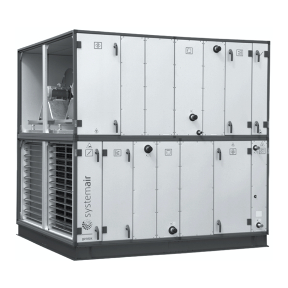
General description, danger and warnings General descriptions, dangers and warnings Geniox air handling units are order specific machines available in thousands of different configurations. Only a few examples of machine configurations are described below. The air handling units are intended for the transport and treatment of air between -40°F and +110°F. The units are exclusively for comfort ventilation. Maintenance of the units must be carried out by skilled technicians. On the drawing below, a right hand unit is shown because the inspection doors are mounted on the right hand side of the unit when looked in direction of SUPPLY airflow. The unit below is with energy recovery wheel. -
Page 11: Geniox Nameplate
General desription danger and warnings Position Description Symbol Damper - supply air Filter - supply air Fan- supply air Heating coil - supply air Fan - return air Energy recovery wheel Filter – return air Damper – return air Integrated control system in a cabinet behind this inspection door. C.1.2 Geniox nameplate Weight of the section. -
Page 12: Pictogram Of A Door For A Fan In A Geniox Unit
General description, danger and warnings C.1.3 Pictogram on a door for a fan in a Geniox unit Example of the pictogram with the symbol for the function - fan. Direction of arrow indicates the direction of the air flow. C.1.4 Pictograms for all available functions in the units Description Symbol GenioxA Vertical Damper GenioxB Horizontal Damper GenioxM Damper for mixing GenioxP Damper for mixing GenioxG Panel filter... -
Page 13: Annex 7 Operator's Guide (How To Use The Systemair Control Panel) (In Separate Cover)
General desription danger and warnings Each of the above has the potential, if misused or handled improperly, to cause bodily injury or death. It is the obligation and responsibility of rigging, installation, and operating/service personnel to identify and recognize these inherent hazards, protect themselves and industry accepted safety practices when working on the units. -
Page 14: Data About The Unit According To Cards And Labels In And On The Unit
General description, danger and warnings Caution labels: CAUTION CAUTION HOT SURFACES INSIDE LOUD NOISE Don’t touch to avoid possible skin WEAR EAR PROTECTION burns. Disconnect and lockout power and allow unit to cool before servicing. ATTENTION ATTENTION NE PAS TOUCHER BRUIT FORT pour éviter d'éventuelles brûlures de PORTER UNE PROTECTION... -
Page 15: Symbols In The Flowchart And Explanation About The Symbols
General desription danger and warnings C.2.2 Symbols in the flowchart and explanation about the symbols Position Description Symbol Temperature sensor Damper actuator – 0-10VDC Filter guard - digital ∆P Pressure transmitter – 0-10VDC Sensor for relative humidity – 0-10VDC Sensor for CO2 – 0-10VDC VFD and drive motor for energy wheel - 0-10V Occupancy Sensor Wheel Rotation Smoke Sensor... -
Page 16: Dimensions Of The Units
Systemair does not assume any responsibility to the safety of the installation/operation, the resulting quality of the process/production, the health of occupants, and/or unit performance if the environment is not suitable to the AHU design. Any misuse of the mechanical structure/components of the air-handler or changes to the final unit build may result in unsafe conditions. Any failure to adhere to the... -
Page 17: Air Handling Unit In Operation
It is recommended that while lifting the Geniox unit (whether provided in sections or a single piece) ,all lifting points be used to prevent uneven weight distribution. Not doing so could result in undue stress being placed on the unit base frame. Offloading and safely rigging the unit is the sole responsibility of the client and not of the factory or Systemair. 3060386 |... -
Page 18: Pre-Assembly Storage
Unit Width Geniox Model Width in (mm) Geniox 10 66.22 (1682) Geniox 12 74.09 (1882) Geniox 15 81.96 (2082) -
Page 19: Outdoor Units - Support Under The Base Frame Of The Unit
To avoid that the unit may tilt during storm the base frame of the unit must be properly fastened to the platform provided by the installer Assembly of Systemair Roof Curb: 1) The roof curb ships knocked down and requires on-site assembly. Each item is labeled to match the layout drawing to determine the location of each piece. -
Page 20: Installation On The Site Of Unit Sections
Instruction for unloading on the site as well as installation and connection G.2.4 Installation on the site of unit sections Caution It is strictly forbidden to lift a section under the top of the section. The plastic corners and brackets are not at all reinforced for lifting the unit under the top. - Page 21 Instruction for unloading on the site as well as installation and connection Note: Never place the strap on the vertical profile too close to a corner, because the plastic corners and the profiles are not reinforced for the heavy load and stress created by the tensioner when a section is pulled along the base frame or on the floor. Place the strap on the bottom profiles of the unit to avoid any When the sections are pulled together, it may be helpful to place load and stress on the vertical profiles when sections are pulled...
-
Page 22: G.2.5 Joining The Ahu Sections
Instruction for unloading on the site as well as installation and connection G.2.5 Joining the AHU sections Position the unit sectional modules directly opposite each other Ensure that the internal factory-fitted rubber sealing is undamaged Section Clamps (Shipped loose) must then be installed using the table below for placement. Side Mount Rule**... - Page 23 Instruction for unloading on the site as well as installation and connection Successful assembly is as shown: Each Geniox Section will have inner reinforcement brackets installed as shown: G.2.5.1 Outdoor Sectional Roof Sealing Outdoor sectional units require sealing where the roof panels meet and therefore the following steps must be taken to ensure a water- tight seal: 1.
-
Page 24: Fan Shipping Bracket Removal
Risk of stack effect by vertical ducts and wind pressure on louvers Important The Systemair air handling units can be ordered and delivered without dampers, and the installer/user must check that duct systems with the described risk of stack effect (chimney effect) will be provided with dampers and spring return motors. -
Page 25: Hood Installation Instructions
Instruction for unloading on the site as well as installation and connection G.2.8 Hood installation instructions Hoods are shipped loose for field install. 1. Apply caulking to hood mating surface, all the way around. 2. Align hood(s) to AHU opening. Ensure appropriate clearance for doors and other access points. 3. Affix the hood(s) to the AHU using sheet metal screws, beginning with uppermost hood. - Page 26 Instruction for unloading on the site as well as installation and connection 3. Seal the double-wall panel on each side with an industrial/ commercial grade silicone sealant or duct seal compound. It is extremely important to seal each panel hole or penetration securely so that it is airtight, watertight, and that there is no exposed foam insulation. Figure: Cutting/Sealing Injected-Foam Insulated panels Geniox Air Handling Unit - User Manual | 3060386...
-
Page 27: Installation - Electrical
Instruction for unloading on the site as well as installation and connection Installation - electrical G.3.1 Description Electrical installations must comply with the current electrical standards of the region the unit is to be installed. Locate unit wiring diagrams inside. Refer to the unit wiring diagrams for position of components, wiring, connection point, and fuse size information. Refer to the unit nameplate for specific electrical information, such as voltage, maximum circuit ampacity (MCA) and maximum overcurrent protection (MOP). -
Page 28: Electrical Connection Of Components And Functions
G.4.4.1 Heating coils Pipes for hot water must be protected by insulation against frost and loss of heat. Pipes, insulation, control system for heating wires and circulation pump are not delivered by Systemair. G.4.4.2 Cooling coils If ordered with the unit, the valves and valve motors are stored in a carton box placed inside the unit. Pipes for cooling must be protected by insulation against condensation on the pipes and loss of cooling in the summer. -
Page 29: Draining Condensate Water
It is important to install drain pan traps to prevent air movement into or out of a blow through or a draw through unit respectively, while also allowing condensate to drain. Systemair recommends installing plugs to ensure ease of cleaning and maintenance of the trap. The figure below with the help of the table illustrates correct trapping, piping and operation of the trap under... -
Page 30: H Start-Up, Adjustments, Use And Commissioning
• Declaration of incorporation – Annex 1 • The unique technical data for this unit - Annex 2 • Wiring diagrams - Annex 16 • Operator’s guide for the Systemair control panel - Annex 17 Start-up by installer All protection and safety measures must be met before start-up of the unit. The main supply voltage must also be checked. The main supply voltage must be measured at the supply terminals in the cabinet. -
Page 31: H.3 Geniox Site Commissioning Template
Star-up, adjustments, use and commissioning H.3 Geniox site commissioning template Date: ____________ Job Name: ______________ Job Address: ______________________________________________________________________________ ________________________________________________________________________________________ Model Number: ___________________________________________________________________________ Serial Number: ____________________________________ Unit Tag: _________________________________ Startup Contractor: _________________________________ Phone: __________________________________ Address: _________________________________________________________________________________ ________________________________________________________________________________________ Pre Startup Check List Installing Items to Verify 1. - Page 32 Star-up, adjustments, use and commissioning Energy Recovery Wheel Assembly Wheel Spin Freely Check Rotation Wheel Motor Amps: _______ No. Wheel Motors L1 (Amps) L2 (Amps) L3 (Amps) Exhaust Fan / Return Fan Assembly Alignment Check Rotation Nameplate Amps: _______ No. Fans L1 (Amps) L2 (Amps) L3 (Amps)
- Page 33 Star-up, adjustments, use and commissioning Distech controller check off list (If applicable) Supply Fan Speed Relief Fan Speed Set point: ___________ Scheduled Times Entered °C °F Temperature Unit of Measure Unit Of Measure Humidity (Hot Gas Reheat) ________% Motion Jumper Remote Inputs (N/A - Not Applicable, A - Analog, D - Digital) Temperature Sensor...
- Page 34 This Log needs to be kept with the unit. It is the responsibility of the owner and/or maintenance/service contractor to document any service, repair or adjustments. Systemair Service are available to advise and provide assistance for proper operation and replacement parts. The responsibility for proper startup, maintenance and servicing of the equipment falls to the owner and qualified licensed tech-...
- Page 35 Star-up, adjustments, use and commissioning 3060386 | Geniox Air Handling Unit - User Manual...
-
Page 36: Description Of Functions
The controller can also work as a stand-alone system without any support from other controllers. H.4.2 Occupied/Unoccupied override With Systemair controls, the Geniox unit can be overridden into occupied mode for testing and commissioning purposes. It can also locally be placed into permanent unoccupied mode for extended period of unoccupied status H.4.3 Valve and valve motor for heating coil The supply voltage for the water valve actuator is 24 VAC, the control signal is 2-10VDC. -
Page 37: Space Pressure Sensors
Star-up, adjustments, use and commissioning H.4.9 Space pressure sensor When room/space pressure control is requested, a differential pressure sensor will be shipped for installation in the field. The pressure sensor will be required to be installed according to the manufacturer’s instruction. H.4.10 Damper actuators The units will be provided with a modulating damper motor with spring return function. They are powered by a 24 VAC signal and are controlled by a 2-10 VDC signal. -
Page 38: I Information About The Residual Risks
Information about the residual risks Information about the residual risks Unit casing I.1.1 Safe means of transport Hazards/dangerous area: • Incorrect handling during transport could result in the unit being dropped and damaged. Dangerous incident: • Dropped Units could result in serious injury or death Claim for reduction of danger: • Correct handling during transportation is described in this manual. If lifted by fork-lift truck the forks of the truck must be sufficiently long. Safety measures are also described in this manual by use of crane. Information about weight of each section is also visible. I.1.2 Common for all unit sections I.1.2.1... -
Page 39: Filters
Information about the residual risks I.1.5 Filters I.1.5.1 Risk caused by missing change of filters Hazards/dangerous area: • Missing change of filters and missing maintenance decrease the capacity and final consequence will be breakdown. Dangerous incident: • By extensive lack of filter change and maintenance the machine can break down. Claim for reduction of danger: • In the manual is the method and schedule for change of filters and maintenance specified. I.1.5.2 Risk caused by the execution of filter change Hazards/dangerous area: • Filter panels and filter bags Dangerous incident: • To breathe in particles that is harmful to the health. -
Page 40: Heating Coils
Instruction on the protective mainteance during repair and maintenance I.1.7 Heating Coils I.1.7.1 Extreme temperatures - heating Hazards/dangerous area: • Electric Heater Manual Reset – 200°F Electric Heater Auto Reset – 125°F • Maximum Temperature for Hot Water Coil and Piping – 200°F Dangerous incident: • Here is no direct risk of burns. (short-time contact – lesser than 2,5 sec). Claim for reduction of danger: • No. I.1.7.2 Extreme temperatures - cooling Hazards/dangerous area: • DX coils and pipes connected to cooling compressor can achieve minus 14 degree Fahrenheit. -
Page 41: M Adjustment And Maintenance Operations
Adjustment and maintenance operations Adjustment and maintenance operations Must be performed by skilled technicians. Shutdown of the unit to a safe state Warning Hazardous Voltage can cause electrical shock and burns. Disconnect power before proceeding with any work on this equipment, observe operating instructions and wear appropriate personal protective equipment (PPE). -
Page 42: Recommended Maintenance Intervals
To maintain same level of fan power consumption for the air-handling unit, it is very important that filters with the same characteristics for start pressure as well as lifetime replace factory-mounted filters. Filter frame for bag filters must be of NON-PVC plastic to ensure safe disposal by incineration. For each individual air handling unit you will find the data for the factory-mounted filters in Annex 2 that is always provided in a cover placed inside the air handling unit when the air handling unit is delivered to the final site. Annex 2 is also always available from Systemair if you can inform us of the production number of the air handling unit. The production number is always printed on the serial plate that is attached to the unit. You will find an example of this serial plate in section d.2.1 of this manual. These air handling units are available with filters sizes mentioned below in the table: Geniox Air Handling Unit - User Manual | 3060386... - Page 43 Adjustment and maintenance operations Panel filter location and size (HxW - Dimensions in inches) Geniox Size Geniox 10 24 x 20 24 x 20 24 x 20 Geniox 12 24 x 20 24 x 20 24 x 20 24 x 12 24 x 12 24 x 12 Geniox 15...
-
Page 44: Bag Filters
Adjustment and maintenance operations Bag filters are available in MERV 9 and 14 rating. Other MERV ratings can also be ordered. Bag filters are 15 inch deep. Panel filters are available in MERV 8 and 13 ratings. Other MERV ratings can also be ordered. 2 inch deep panel filters are available as a standard option. 4 inch deep panel can also be ordered. Note: Special sizes of filters and MERV ratings are available from Camfil. M.4.1 Bag filters Turn the unit off and wait for 2 minutes until unit completely stops. Used filters can be pulled out. Store the used filters immediately in plastic bags to avoid polluting the environment with dust particulates. Geniox units in the sizes 15 – 25 are provided with a very corro- sive-resistant and reliable system, where filters are slid into the units in a lower and upper durable U-profile of plastic/rubber. Check the upper and lower U-profile for damage and check the vertical rubber profile on the back wall as well as the rubber profile on the inspec- tion door for damage. The new filter bags must be pushed carefully into the unit in order to ensure that they are sealed properly. The filters must have vertical bags. - Page 45 Adjustment and maintenance operations Place the self-adhesive strip on one vertical side of the filter fame Check that the end of the strip is fully even with the horizontal side of the filter frame. Remove excess of the strip. The end of the strip must be fully even with the horizontal side of the filter frame. Push the filters carefully in the U-profile to be sure that there are no leakages between the filters. Check that the vertical side of the last filter in the U-profile is fully even with the end of the U-profile. If the end of the last filter is not fully even with the end of the U-profile an additional self-adhesive profile must be added to avoid any gap between the rubber profile on the inspection door and the last filter. 3060386 | Geniox Air Handling Unit - User Manual...
-
Page 46: Panel Filters
Adjustment and maintenance operations The end of the last filter is fully even with the end of the U-pro- file. The rubber profile on the inspection door will close the gap between inspection door and filter. Job is done. Check that rubber profiles on the back panel as well as rubber profiles on the inspection door are without wear and damage — still sufficient for avoiding any air leakage. M.4.2 Panel filters The filter cell guide rails are to be cleaned before fitting the new filters. Geniox Air Handling Unit - User Manual | 3060386... -
Page 47: Other Components To Maintain
Adjustment and maintenance operations Other Components to maintain M.5.1 The unit It is very easy to remove inspection doors for access to cleaning, service, repairs and replacement of components in the unit. Lift the stainless steel shaft in the hinge to remove the door The unit should be cleaned once a year when operating with normal air quality for comfort ventilation with no special hygiene require- ments. -
Page 48: Energy Recovery Wheel
Adjustment and maintenance operations The damper blades are fitted with synthetic bearings requiring no lubrication. Air-tightness of the damper, when the damper motor is in the closed position, must be visually checked once a year. The damper motor is to be adjusted if the damper does not close tightly. M.5.3 Energy recovery wheel The energy wheel is to be checked at least once a year to ensure that it can turn freely and easily. This can be done by removing the belt drive at the motor and then turning the rotor manually with a hand on the peripheral wheel casing. -
Page 49: Plug Fans
Instructions to enable adjustment and maintenance safely M.5.10 Plug fans Dust can accumulate on the fan impeller which can cause imbalance and vibrations. The fan impeller must therefore be checked once a year and cleaned, if necessary. Anti-vibration mounts and flexible connections should be checked at the same time. If the anti-vibration mounts are damaged in any way they must be replaced. M.5.11 Motor The motor are usually fitted with factory lubricated bearings which require no further lubrication. Larger motors can be fitted with... -
Page 50: Personal Protective Equipment For Maintenance Staff - Health And Safety
| Instructions to enable adjustment and maintenance safely N.1.2 Personal protective equipment for maintenance staff – health and safety Use the below-mentioned personal protective equipment for maintenance: • Cut-resistant gloves for protection against injury from sharp metal plate edges. • Hard Hat • Particulate respirator – maintenance free including foam face-seal and adjustable pre-threaded headbands – for replacing filters. • Padlock for locking the above mentioned automatic circuit breakers. Geniox Air Handling Unit - User Manual | 3060386... -
Page 51: Annex
Annex Geniox Air handling unit User Manual Document in original language | Part number of this manual 3060386... - Page 52 Roof curb master tables..................................5-1 Annex 6 Wiring diagram (in separate cover) ............................6-1 Annex 7 Operator’s guide (how to use the Systemair control panel) (in separate cover)..............7-1 Geniox Air Handling Unit - User Manual | 3060386...
-
Page 53: Annex 3 Spare Part List
Spare part list Annex 3 Spare part list Printed on separate pages but not delivered with every unit. Available on demand. Instructions for use: This spare parts list contains no safety regulations and is merely intended to assist in the ordering of spare parts. For information about operating, servicing, or repairing, the relevant safety and operating instructions must be consulted at all costs. -
Page 54: Annex 4 Erw Maintenance
A seal lacquer without cracks is the indication that bolts and screws have not loosen. If a wheel bearing ever needs replacement, please consult Systemair for parts and instructions. ERW Belt tensioner The belt tensioner is fastened to an aluminum plate aligned with the wheel motor. - Page 55 ERW maintenance Belt tensioner replacement The belt tensioner replacement is achieved by following these simple steps: 1) Lift the locking pin while pushing down on the motor to release the belt tension (a). 2) Incline the motor to remove the belt around the tensioner (b). 3) Unscrew the belt tensioner (c).
- Page 56 ERW maintenance Belt Installation To install a spare belt or reduce the length of the current belt, follow these 5 easy steps: 1. Open/separate the belt by twisting the link tabs sideways and pulling the surplus out of the belt (see image below). If needed, adjust the length of the belt by replacing or removing the undesired links.
- Page 57 ERW maintenance 3. Pull the belt tightly around the wheel and the gear reducer’s pulley. Connect both ends of the belt (see above image d. to a.). 4. Pass the belt over the tensioner idler sheave and place the motor to its initial position (a). 5.
- Page 58 ERW maintenance HEEL EDIA ORRECT 0" (S TART HEEL OLERANCE RONG RONG CLOSE IR0005 PERIPHERAL S-TYPE SEAL The S-type labyrinth peripheral seal is a non-contact seal fixed to the face plate of the unit.The seal overlaps inside the rotor casing for increase airtightness. It is factory installed and adjusted. No seal adjustment is required in the field. LOW FRICTION SIDE & CENTER The low friction side and center seal are contact seals fixed to the wheel frame. The middle seals are located behind the pillow block bearings. The side seals are installed on the side of the rotor, along the depth dimension. They are factory installed and adjusted. No seal adjustment is required in the field.
- Page 59 ERW maintenance Media Cleaning Due to their inner laminar flow and self-cleaning feature, the I4 wheels are resistant to dust build-ups. As no particle will accumulate inside the media, only the edges need to be cleaned. If the wheel application is such that cleaning is needed, a vacuum cleaner with soft brush tip and compressed air with a flat nozzle blowgun (70 psi) is recommended to clean both sides of the media. As a last step, a microfiber humid cloth can be used to wipe the surface of the wheel. It is not recommended to use any type of solvent or detergent on the energy recovery wheel. Caution While cleaning the wheel media, take care not to apply too much pressure to avoid damaging the wheel surface.
- Page 60 Wheel bearing lubrication Bearing bolt tightness Driving belt tension and wear* AirLoop seals adjustment Service parts If part replacement is required, please contact service@systemair.net. For technical support, send pictures and summary explanation of the current situation. ERW Diameter Ref no. Seal Driving belt 12’...
- Page 61 ERW maintenance 3060386 | Geniox Air Handling Unit - User Manual...
-
Page 62: Roof Curb Master Tables
Roof curb master tables Geniox Air Handling Unit - User Manual | 3060386... - Page 63 Roof curb master tables 3060386 | Geniox Air Handling Unit - User Manual...
- Page 64 Roof curb master tables Geniox Air Handling Unit - User Manual | 3060386...
- Page 65 Roof curb master tables 3060386 | Geniox Air Handling Unit - User Manual...
- Page 66 Systemair NA 8 Rouse Street, Tillsonburg, ON, N4G 5W8 Toll free : 800.688.6363...
Need help?
Do you have a question about the Geniox 10 and is the answer not in the manual?
Questions and answers