
Related Manuals for Huawei UPS5000-E-400K-SMS


Summary of Contents for Huawei UPS5000-E-400K-SMS
- Page 1 UPS5000-E-(400 kVA-600 kVA) User Manual (60 kVA Power Modules) Issue Date 2022-06-20 HUAWEI DIGITAL POWER TECHNOLOGIES CO., LTD.
- Page 2 Notice The purchased products, services and features are stipulated by the contract made between Huawei Digital Power Technologies Co., Ltd. and the customer. All or part of the products, services and features described in this document may not be within the purchase scope or the usage scope. Unless otherwise specified in the contract, all statements, information, and recommendations in this document are provided "AS IS"...
-
Page 3: About This Document
Indicates a hazard with a low level of risk which, if not avoided, could result in minor or moderate injury. Issue 07 (2022-06-20) Copyright © Huawei Digital Power Technologies Co., Ltd. - Page 4 Added descriptions about the SNMP in the site configuration section. 2019-08-16 Updated the recommended power cables. 2019-02-27 Improved descriptions about the USB port. 2022-05-12 Updated some MDU screenshots. 2018-08-15 This issue is the first official release. Issue 07 (2022-06-20) Copyright © Huawei Digital Power Technologies Co., Ltd.
-
Page 5: Table Of Contents
2.3.5 Control Module.................................. 35 2.3.5.1 Overview................................... 35 2.3.5.2 ECM..................................... 36 2.3.5.3 Dry contact card................................38 2.3.5.4 Monitoring Interface Card............................40 2.3.6 MDU....................................... 45 2.3.6.1 MDU (with a Flat LCD)..............................45 Issue 07 (2022-06-20) Copyright © Huawei Digital Power Technologies Co., Ltd. - Page 6 4.1.4 Powering On Loads................................ 105 4.1.5 (Optional) Setting Parameters for the BCB Box....................105 4.2 Shutting Down and Powering Off the UPS....................... 106 4.3 Starting the UPS in Battery Mode..........................108 Issue 07 (2022-06-20) Copyright © Huawei Digital Power Technologies Co., Ltd.
- Page 7 7.5 Mains Input Electrical Specifications........................... 132 7.6 Bypass Input Electrical Specifications.......................... 132 7.7 Battery Electrical Specifications............................. 133 7.8 Output Electrical Specifications............................. 133 7.9 System Electrical Specifications............................. 134 A Acronyms and Abbreviations................... 136 Issue 07 (2022-06-20) Copyright © Huawei Digital Power Technologies Co., Ltd.
-
Page 8: Safety Information
Failure to follow the operation instructions and safety precautions on the product and in this document ● Equipment damage due to force majeure, such as earthquakes, fire, and storms Issue 07 (2022-06-20) Copyright © Huawei Digital Power Technologies Co., Ltd. - Page 9 Keep irrelevant people away from the equipment. Only operators are allowed to access the equipment. ● Use insulated tools or tools with insulated handles, as shown in the following figure. Issue 07 (2022-06-20) Copyright © Huawei Digital Power Technologies Co., Ltd.
- Page 10 Do not change the structure or installation sequence of equipment without permission. ● Do not touch a running fan with your fingers, components, screws, tools, or boards before the fan is powered off or stops running. Issue 07 (2022-06-20) Copyright © Huawei Digital Power Technologies Co., Ltd.
-
Page 11: Personnel Requirements
Do not operate the equipment in the absence of a properly installed ground conductor. ● Ensure that the equipment is connected permanently to the protective ground. Before operating the equipment, check its electrical connection to ensure that it is securely grounded. Issue 07 (2022-06-20) Copyright © Huawei Digital Power Technologies Co., Ltd. - Page 12 0°C. Handle cables with caution, especially at a low temperature. – Cables stored at subzero temperatures must be stored at room temperature for at least 24 hours before they are laid out. Issue 07 (2022-06-20) Copyright © Huawei Digital Power Technologies Co., Ltd.
-
Page 13: Installation Environment Requirements
Install the equipment in an area far away from liquids. Do not install it under areas prone to condensation, such as under water pipes and air exhaust vents, or areas prone to water leakage, such as air conditioner vents, ventilation Issue 07 (2022-06-20) Copyright © Huawei Digital Power Technologies Co., Ltd. - Page 14 Any violations must be promptly pointed out by the site manager or safety supervisor and the involved personnel should be prompted for correction. Personnel who fail to stop violations will be forbidden from working. Issue 07 (2022-06-20) Copyright © Huawei Digital Power Technologies Co., Ltd.
-
Page 15: Mechanical Safety
Ensure that the wider end of the ladder is at the bottom, or protective measures have been taken at the bottom to prevent the ladder from sliding. Issue 07 (2022-06-20) Copyright © Huawei Digital Power Technologies Co., Ltd. - Page 16 When pulling the equipment out of a cabinet, be aware of unstable or heavy objects on the cabinet to prevent injury. ● Be cautious to avoid injury when moving heavy objects. Issue 07 (2022-06-20) Copyright © Huawei Digital Power Technologies Co., Ltd.
-
Page 17: Device Running Safety
The UPS operating environment must meet the requirements for the climate indicator, mechanically active substance indicator, and chemically active substance indicator in ETSI EN 300 019-1 class 3.6. Issue 07 (2022-06-20) Copyright © Huawei Digital Power Technologies Co., Ltd. - Page 18 UPS is connected to a backfeed protection card. Disconnect the backfeed protection card from the UPS before operating the UPS. Do not use the UPS in the following places: Issue 07 (2022-06-20) Copyright © Huawei Digital Power Technologies Co., Ltd.
-
Page 19: Battery Safety
Dispose of waste batteries in accordance with local laws and regulations. Do not dispose of batteries as household waste. If a battery is disposed of improperly, it may explode. Issue 07 (2022-06-20) Copyright © Huawei Digital Power Technologies Co., Ltd. - Page 20 ● To prevent fire or corrosion, ensure that flammable gas (such as hydrogen) is properly exhausted for lead-acid batteries. Lead-acid batteries in use emit flammable gas. Ensure that batteries are kept in a well-ventilated area and take preventive measures against fire. Issue 07 (2022-06-20) Copyright © Huawei Digital Power Technologies Co., Ltd.
- Page 21 ● Do not throw a lithium battery in fire. ● When maintenance is complete, return the waste lithium battery to the maintenance office. Issue 07 (2022-06-20) Copyright © Huawei Digital Power Technologies Co., Ltd.
-
Page 22: Others
UPS output voltage level or frequency. Doing so may affect the power supply to equipment. ● Exercise caution when setting battery parameters. Incorrect settings will affect the power supply and battery lifespan. Issue 07 (2022-06-20) Copyright © Huawei Digital Power Technologies Co., Ltd. -
Page 23: Overview
500 kVA (full ● UPS5000-E-500K-FMS configuration) ● UPS5000-E-500K-FMS-01 600 kVA (standard ● UPS5000-E-600K-SMS configuration) ● UPS5000-E-600K-SMS-01 600 kVA (full ● UPS5000-E-600K-FMS configuration) ● UPS5000-E-600K-FMS-01 Figure 2-1 UPS model number Issue 07 (2022-06-20) Copyright © Huawei Digital Power Technologies Co., Ltd. -
Page 24: Working Principle
The UPS5000 adopts intelligent control. Its power module consists of a rectifier, inverter, and DC/DC converter. The UPS5000 converts inputs into pure high-quality sine wave outputs by using the high- frequency switching technology. Issue 07 (2022-06-20) Copyright © Huawei Digital Power Technologies Co., Ltd. -
Page 25: Working Modes
In normal mode, the rectifier converts AC power into DC power, and then the inverter converts the DC power into high-precision AC outputs. The conversions protect loads from interference such as input harmonics, glitches, and voltage transients. Issue 07 (2022-06-20) Copyright © Huawei Digital Power Technologies Co., Ltd. -
Page 26: Bypass Mode
In bypass mode, loads are powered by the bypass module. The bypass power supply is not protected by the UPS and therefore is prone to the mains outage, abnormal AC voltage waveform, or abnormal frequency. Issue 07 (2022-06-20) Copyright © Huawei Digital Power Technologies Co., Ltd. -
Page 27: Battery Mode
If the mains input is abnormal or the rectifier becomes abnormal, the UPS transfers to battery mode. The power module obtains DC power from batteries, and the power is converted into AC output by the inverter. Issue 07 (2022-06-20) Copyright © Huawei Digital Power Technologies Co., Ltd. -
Page 28: Maintenance Bypass Mode
2.2.2.4 Maintenance Bypass Mode When the UPS works in maintenance bypass mode, the current flows through the maintenance bypass instead of the power module. You can maintain the circuit inside the cabinet. Issue 07 (2022-06-20) Copyright © Huawei Digital Power Technologies Co., Ltd. -
Page 29: Eco Mode
UPS transfers from bypass mode to inverter mode. In bypass mode or normal mode, the rectifier keeps working and charges batteries using a charger. The ECO mode delivers a high efficiency. Issue 07 (2022-06-20) Copyright © Huawei Digital Power Technologies Co., Ltd. -
Page 30: Product Introduction
Figure 2-7 UPS conceptual diagram in ECO mode NO TE Manual startup is required to ensure that the inverter is in standby state and the power flow has reached the inverter. 2.3 Product Introduction Issue 07 (2022-06-20) Copyright © Huawei Digital Power Technologies Co., Ltd. -
Page 31: Appearance
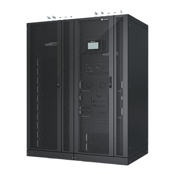
UPS5000-E-(400 kVA-600 kVA) User Manual (60 kVA Power Modules) 2 Overview 2.3.1 Appearance Figure 2-8 400 kVA/500 kVA UPS (1) Power cabinet (2) Anchor baffle plate (3) MDU (4) Bypass cabinet Issue 07 (2022-06-20) Copyright © Huawei Digital Power Technologies Co., Ltd. - Page 32 UPS5000-E-(400 kVA-600 kVA) User Manual (60 kVA Power Modules) 2 Overview Figure 2-9 600 kVA UPS (1) Power cabinet (2) Anchor baffle plate (3) MDU (4) Bypass cabinet Issue 07 (2022-06-20) Copyright © Huawei Digital Power Technologies Co., Ltd.
-
Page 33: Product Structure
2.3.2 Product Structure Figure 2-10 Product structure (400 kVA, standard configuration) (1) Power modules (2) Control module (3) Power distribution module cover (4) Maintenance bypass switch (5) Bypass module Issue 07 (2022-06-20) Copyright © Huawei Digital Power Technologies Co., Ltd. - Page 34 (1) Power modules (2) Control module (3) Power distribution module cover (4) Maintenance bypass switch (5) Bypass module (6) Mains input switch (7) Output switch (8) Bypass input switch Issue 07 (2022-06-20) Copyright © Huawei Digital Power Technologies Co., Ltd.
- Page 35 User Manual (60 kVA Power Modules) 2 Overview Figure 2-12 Product structure (500 kVA, standard configuration) (1) Power modules (2) Control module (3) Power distribution module cover (4) Maintenance bypass switch (5) Bypass module Issue 07 (2022-06-20) Copyright © Huawei Digital Power Technologies Co., Ltd.
- Page 36 (1) Power modules (2) Control module (3) Power distribution module cover (4) Maintenance bypass switch (5) Bypass module (6) Mains input switch (7) Output switch (8) Bypass input switch Issue 07 (2022-06-20) Copyright © Huawei Digital Power Technologies Co., Ltd.
- Page 37 User Manual (60 kVA Power Modules) 2 Overview Figure 2-14 Product structure (600 kVA, standard configuration) (1) Power modules (2) Control module (3) Power distribution module cover (4) Maintenance bypass switch (5) Bypass module Issue 07 (2022-06-20) Copyright © Huawei Digital Power Technologies Co., Ltd.
-
Page 38: Power Module
The power module consists of a power factor correction (PFC) rectifier and inverter. It performs AC/DC or DC/DC conversion on the mains and battery inputs, and stabilizes the bus voltage. The inverter (DC/AC) converts the inputs into sine wave outputs. Issue 07 (2022-06-20) Copyright © Huawei Digital Power Technologies Co., Ltd. - Page 39 (blinking at 4 Hz, on for 0.125s and off for 0.125s). The rectifier CPLD software is being upgraded. Alarm Yellow Steady on A minor alarm is generated for the indicator inverter or rectifier. Issue 07 (2022-06-20) Copyright © Huawei Digital Power Technologies Co., Ltd.
-
Page 40: Bypass Module
The power module overload exceeds the time limit. Both the active and standby energy control modules (ECMs) are abnormal. The system fails to run properly. The power supply is switched to the bypass manually. Issue 07 (2022-06-20) Copyright © Huawei Digital Power Technologies Co., Ltd. - Page 41 (blinking at 4 Hz, on for 0.125s and off for 0.125s). The bypass CPLD software is being upgraded. Alarm indicator Yellow Steady on A minor alarm is generated for the bypass. Issue 07 (2022-06-20) Copyright © Huawei Digital Power Technologies Co., Ltd.
-
Page 42: Control Module
ECM 2 (9) Indicators for ECM (10) Dry contact card (11) Dry contacts (12) MDU port (13) RS485 port (14) Fast Ethernet (FE) (15) COM2 port (16) COM1 port port Issue 07 (2022-06-20) Copyright © Huawei Digital Power Technologies Co., Ltd. -
Page 43: Ecm
NO TE For a single UPS, the parallel cable is not needed. Table 2-8 Indicator description Indicator Color Status Description NORMAL Green Steady This ECM is the active ECM. Issue 07 (2022-06-20) Copyright © Huawei Digital Power Technologies Co., Ltd. - Page 44 UPS5000 status information to other monitoring modules. ● The system provides three types of CAN communication: monitoring CAN communication, intra-rack parallel CAN communication, and inter-rack parallel CAN communication. Issue 07 (2022-06-20) Copyright © Huawei Digital Power Technologies Co., Ltd.
-
Page 45: Dry Contact Card
● Disconnected: no battery grounding Port for signal fault ground Port for detecting ● Connected: DG Disconnected diesel generator mode (DG) mode ● Disconnected: non- DG mode Port for signal ground Issue 07 (2022-06-20) Copyright © Huawei Digital Power Technologies Co., Ltd. - Page 46 STATUS_0V ground SWITCH Port for monitoring ● Connected: circuit Connected STATUS_BP the bypass input breaker ON circuit breaker ● Disconnected: circuit breaker OFF SWITCH Port for signal STATUS_0V ground Issue 07 (2022-06-20) Copyright © Huawei Digital Power Technologies Co., Ltd.
-
Page 47: Monitoring Interface Card
MDU. The monitoring interface card provides the ambient temperature and humidity sensor port, FE port, battery temperature monitoring port, and network management port. The MDU monitors the UPS, Issue 07 (2022-06-20) Copyright © Huawei Digital Power Technologies Co., Ltd. - Page 48 Connects to an indoor battery temperature sensor. temperature sensor port Southbound COM1 ● Supported protocol: Modbus-RTU. communicati ● Connects to an ambient temperature and ons port 1 humidity sensor over two wires. Issue 07 (2022-06-20) Copyright © Huawei Digital Power Technologies Co., Ltd.
- Page 49 ● RS485 cables and FE cables must be shielded cables. Figure 2-23 Figure 2-24 are recommended wiring methods for DO ports. Figure 2-23 Wiring method 1 Figure 2-24 Wiring method 2 Issue 07 (2022-06-20) Copyright © Huawei Digital Power Technologies Co., Ltd.
- Page 50 User Manual (60 kVA Power Modules) 2 Overview Figure 2-25 COM1 pins Table 2-11 COM1 pin definition Description RS485- RS485+ 12V_PORT Figure 2-26 COM2 pins Table 2-12 COM2 pin definition Description RS485+ RS485- Issue 07 (2022-06-20) Copyright © Huawei Digital Power Technologies Co., Ltd.
- Page 51 UPS5000-E-(400 kVA-600 kVA) User Manual (60 kVA Power Modules) 2 Overview Description RS485+ RS485- CANH0 CANL0 Figure 2-27 RS485 pins Table 2-13 RS485 pin definition Description RS485_T+ RS485_T– RS485_R+ RS485_R– Issue 07 (2022-06-20) Copyright © Huawei Digital Power Technologies Co., Ltd.
-
Page 52: Mdu
2.3.6 MDU NO TE There are two types of MDUs: ● If the device model is UPS5000-E-400K-SMS-01, UPS5000-E-400K-FMS-01, UPS5000- E-500K-SMS-01, UPS5000-E-500K-FMS-01, UPS5000-E-600K-SMS-01, or UPS5000- E-600K-FMS-01, the MDU has a flat LCD. ● If the device model is UPS5000-E-400K-SMS, UPS5000-E-400K-FMS, UPS5000-E-500K- SMS, UPS5000-E-500K-FMS, UPS5000-E-600K-SMS, or UPS5000-E-600K-FMS, the MDU has an indented LCD. - Page 53 Figure 2-29 MDU ports Table 2-15 Port description Port Name Description MUS05A Connects to the MDU and monitoring interface card (DB26) Network port Reserved RS485_1 Reserved FE_1 Reserved FE_2 Reserved Issue 07 (2022-06-20) Copyright © Huawei Digital Power Technologies Co., Ltd.
-
Page 54: Mdu (With An Indented Lcd)
Dimensions (H x W x D): 175 mm x 264 mm x 40 mm 2.3.6.2 MDU (with an Indented LCD) Appearance Figure 2-30 MDU (with an indented LCD) (1) Status indicator (2) LCD touchscreen Issue 07 (2022-06-20) Copyright © Huawei Digital Power Technologies Co., Ltd. - Page 55 The indicator on the LCD panel is yellow when the bypass supplies power in non-ECO mode. Figure 2-31 MDU ports Table 2-17 MDU port description Port Name Description MUS05A (DB26) Connects the MDU and monitoring interface card Network port Reserved RS485_1 Reserved Issue 07 (2022-06-20) Copyright © Huawei Digital Power Technologies Co., Ltd.
-
Page 56: Typical Configurations
Single UPS Supplies power to common loads. Parallel system Supplies power to important loads in small- and medium- sized data centers. It features high availability and strong transient overload capability. Issue 07 (2022-06-20) Copyright © Huawei Digital Power Technologies Co., Ltd. -
Page 57: Single Ups
UPSs are connected over parallel cables to synchronize UPS outputs to supply power to loads. If one UPS fails, the other UPSs continue supplying power to loads. Figure 2-32 Conceptual diagram of an N+X parallel system Issue 07 (2022-06-20) Copyright © Huawei Digital Power Technologies Co., Ltd. -
Page 58: Dual-Bus System
Installed when the UPS is equipped with subrack a backfeed protection card and dry contact extended card. Dry contact Provides extended monitoring ports: five extended card relay output ports and five input ports. Issue 07 (2022-06-20) Copyright © Huawei Digital Power Technologies Co., Ltd. - Page 59 ● The ECM extended subrack does not support onsite installation. If you require this optional component, inform the Company when you purchase the UPS so that it can install the subrack before delivery. Issue 07 (2022-06-20) Copyright © Huawei Digital Power Technologies Co., Ltd.
-
Page 60: Installation
UPS5000-E-(400 kVA-600 kVA) User Manual (60 kVA Power Modules) 3 Installation Installation 3.1 Installation Preparations 3.1.1 Site 3.1.1.1 UPS Dimensions Figure 3-1 Dimensions (400 kVA/500 kVA, unit: mm) Issue 07 (2022-06-20) Copyright © Huawei Digital Power Technologies Co., Ltd. -
Page 61: Installation Environment
Reserve a clearance of at least 500 mm from the rear of the cabinets for ventilation. If the UPS will be operated from the rear, reserve a clearance of at least 800 mm for operations. Issue 07 (2022-06-20) Copyright © Huawei Digital Power Technologies Co., Ltd. -
Page 62: Tools And Instruments
Prepare the following tools and meters indicated in Table 3-1 for installation. Table 3-1 Tools and instruments Tools and Instruments Electric pallet Manual pallet Ladder Rubber mallet truck truck Issue 07 (2022-06-20) Copyright © Huawei Digital Power Technologies Co., Ltd. - Page 63 Level instrument Insulation tape Cotton cloth Label Electrician's knife Electrostatic Protective gloves Insulated gloves Insulation discharge (ESD) protective shoes gloves Torque Cable cutter Brush Flat-head screwdriver screwdriver (2–5 mm) Issue 07 (2022-06-20) Copyright © Huawei Digital Power Technologies Co., Ltd.
-
Page 64: Preparing Power Cables
Input current (A) input Recommende 2 x (4 x 185) 3 x (4 x 185) 3 x (4 x 240) d cross- sectional area Bypass Input current (A) input Issue 07 (2022-06-20) Copyright © Huawei Digital Power Technologies Co., Ltd. - Page 65 The maximum battery discharge current refers to the current when forty 12 V batteries in standard configuration, that is, two hundred and forty 2 V battery cells (1.67 V/cell), stop discharging. Issue 07 (2022-06-20) Copyright © Huawei Digital Power Technologies Co., Ltd.
- Page 66 Battery Crimped DT 18 mm 50 mm 120 N·m input terminal Output Crimped DT 18 mm 50 mm 120 N·m terminal Crimped DT 35 mm 47 N·m terminal Issue 07 (2022-06-20) Copyright © Huawei Digital Power Technologies Co., Ltd.
- Page 67 ● If multiple loads are connected, specifications for branch circuit breakers must not exceed the recommended specifications. ● Select proper circuit breakers to protect loads and cables, and cascade them properly to achieve selective protection. Issue 07 (2022-06-20) Copyright © Huawei Digital Power Technologies Co., Ltd.
-
Page 68: Unpacking
Step 2 Remove the UPS outer packing. Step 3 Remove the bolts that secure the UPS to the pallet and remove the UPS from the pallet. Figure 3-4 Removing the pallet from the UPS ----End Issue 07 (2022-06-20) Copyright © Huawei Digital Power Technologies Co., Ltd. -
Page 69: Single Ups Installation
Step 1 Determine the cabinet installation positions on the floor based on the holes in the marking-off template for floor installation. NO TE ● A: mounting holes on the channel steel ● B: mounting holes on the floor Issue 07 (2022-06-20) Copyright © Huawei Digital Power Technologies Co., Ltd. - Page 70 Knock the expansion bolt into the hole until the expansion sleeve completely fits into the hole. The expansion sleeve must be completely buried under the ground to facilitate subsequent installation. Issue 07 (2022-06-20) Copyright © Huawei Digital Power Technologies Co., Ltd.
- Page 71 Step 4 Use M12x60 expansion bolts to secure the cabinet to the expansion bolt mounting holes on the floor. Figure 3-8 Tightening expansion bolts Step 5 Install the front, rear, left, and right anchor baffle plates. Issue 07 (2022-06-20) Copyright © Huawei Digital Power Technologies Co., Ltd.
-
Page 72: Installation On Channel Steel
Step 1 Determine the cabinet installation positions on the channel steel based on holes in the marking-off template for channel steel installation. NO TE ● A: mounting holes on the channel steel ● B: mounting holes on the floor Issue 07 (2022-06-20) Copyright © Huawei Digital Power Technologies Co., Ltd. - Page 73 Step 4 Use common M12x60 bolts to secure the cabinet into the mounting holes in the channel steel and tighten the bolts. Step 5 Install the front, rear, left, and right anchor baffle plates. ----End Issue 07 (2022-06-20) Copyright © Huawei Digital Power Technologies Co., Ltd.
-
Page 74: Installing Batteries
● Select the mounting holes for leveling feet based on the cabinet width onsite. Figure 3-12 Installing leveling feet Step 2 Secure the IP21 component to the top of each cabinet. Issue 07 (2022-06-20) Copyright © Huawei Digital Power Technologies Co., Ltd. -
Page 75: Connecting An Ambient T/H Sensor
Step 1 Connect the RJ11 port on the ambient T/H sensor to the COM1 port on the monitoring interface card. Figure 3-14 Connecting a UPS and an ambient T/H sensor NO TE The ambient T/H sensor can be used as a battery temperature sensor. ----End Issue 07 (2022-06-20) Copyright © Huawei Digital Power Technologies Co., Ltd. -
Page 76: Ups Cable Connection Reference
Choose an appropriate cabling route based on the actual situation. The figure is for reference only. Step 4 Connect the cable with a crimped terminal to the corresponding copper bar. Step 5 Clean foreign matter inside the cabinet. ----End Issue 07 (2022-06-20) Copyright © Huawei Digital Power Technologies Co., Ltd. -
Page 77: Routing Cables
● The figures are for reference only. For more information about the recommended cable cross-sectional area and quantity, refer to 3.1.3 Preparing Power Cables and site requirements. Issue 07 (2022-06-20) Copyright © Huawei Digital Power Technologies Co., Ltd. - Page 78 User Manual (60 kVA Power Modules) 3 Installation Figure 3-16 Power distribution module (400 kVA UPS, 500 kVA UPS) (1) Mains input (2) Battery input (3) Output terminal (4) Bypass input terminal terminal terminal Issue 07 (2022-06-20) Copyright © Huawei Digital Power Technologies Co., Ltd.
- Page 79 (3) Output terminal (4) Bypass input terminal terminal terminal Procedure Step 1 Open the front door of the bypass cabinet and remove the covers of the power distribution subrack. Issue 07 (2022-06-20) Copyright © Huawei Digital Power Technologies Co., Ltd.
- Page 80 Figure 3-19 Removing the top cable covers Step 3 Remove the rear cover from the bypass cabinet. NO TE You are advised to remove the side panel from the bypass cabinet before connecting cables. Issue 07 (2022-06-20) Copyright © Huawei Digital Power Technologies Co., Ltd.
- Page 81 The protective covers need to be reinstalled after the connecting copper bars are removed. Figure 3-20 Removing the copper bar protective covers at the rear Issue 07 (2022-06-20) Copyright © Huawei Digital Power Technologies Co., Ltd.
- Page 82 ● Before cable connections, ensure that all UPS input switches are OFF. Paste warning labels to prevent operation on the switches. ● Connect input power cables to the UPS and then to customer equipment. Issue 07 (2022-06-20) Copyright © Huawei Digital Power Technologies Co., Ltd.
- Page 83 3 Installation Figure 3-22 Ground cable Step 6 Connect the mains input power cables. Figure 3-23 Connecting the mains input power cables Step 7 Connect the output power cables. Issue 07 (2022-06-20) Copyright © Huawei Digital Power Technologies Co., Ltd.
- Page 84 Figure 3-24 Connecting AC output power cables Step 8 Connect the bypass input power cables. (Perform this step only when the mains input and bypass input use different power sources.) Issue 07 (2022-06-20) Copyright © Huawei Digital Power Technologies Co., Ltd.
- Page 85 ● The battery voltage may result in serious injury. Observe safety precautions when connecting cables. ● Ensure that cables are correctly connected between battery strings and the battery switch, and between the battery switch and the UPS. Avoid inverse connections. Issue 07 (2022-06-20) Copyright © Huawei Digital Power Technologies Co., Ltd.
- Page 86 20 batteries. Figure 3-27 Neutral wire Step 10 Route signal cables. Bind cables to the cabinet. Figure 3-28 shows the signal cables routed from the top of the cabinet. Issue 07 (2022-06-20) Copyright © Huawei Digital Power Technologies Co., Ltd.
- Page 87 ● After connecting cables, check that a certain clearance is reserved between the internal switch (if any) extension pole and power cables to avoid friction. Issue 07 (2022-06-20) Copyright © Huawei Digital Power Technologies Co., Ltd.
-
Page 88: Bottom Cable Routing
Step 2 Remove the cable covers from the bottom of the cabinet, drill holes in the covers, attach grommet strips to the hole edges for protecting cables, and reinstall the cable covers. NO TE The hole size and quantity are for reference only. Issue 07 (2022-06-20) Copyright © Huawei Digital Power Technologies Co., Ltd. - Page 89 Step 5 Connect a ground cable to the UPS. CA UTION If you do not ground the UPS as required, electromagnetic interference, electric shocks, or fire may occur. Issue 07 (2022-06-20) Copyright © Huawei Digital Power Technologies Co., Ltd.
- Page 90 ● Connect the input power cables to the UPS before connecting power cables to customer equipment. Figure 3-30 Grounding Step 6 Connect the bypass input power cables. (Perform this step only when the mains input and bypass input use different power sources.) Issue 07 (2022-06-20) Copyright © Huawei Digital Power Technologies Co., Ltd.
- Page 91 Step 7 Connect the output power cables. CA UTION After connecting the output power cables, if loads are not ready to be powered, insulate the terminals of the output power cables. Issue 07 (2022-06-20) Copyright © Huawei Digital Power Technologies Co., Ltd.
- Page 92 UPS5000-E-(400 kVA-600 kVA) User Manual (60 kVA Power Modules) 3 Installation Figure 3-32 Connecting output power cables Step 8 Connect the mains input power cables. Issue 07 (2022-06-20) Copyright © Huawei Digital Power Technologies Co., Ltd.
- Page 93 ● The battery voltage may result in serious injury. Observe safety precautions when connecting cables. ● Ensure that cables are correctly connected between battery strings and the battery switch, and between the battery switch and the UPS. Avoid inverse connections. Issue 07 (2022-06-20) Copyright © Huawei Digital Power Technologies Co., Ltd.
- Page 94 20 batteries. Figure 3-35 Neutral wire Step 10 Route signal cables. Bind cables to the cabinet. Figure 3-36 shows the signal cables routed from the bottom of the cabinet. Issue 07 (2022-06-20) Copyright © Huawei Digital Power Technologies Co., Ltd.
- Page 95 ● After connecting cables, check that a certain clearance is reserved between the internal switch (if any) extension pole and power cables to avoid friction. Issue 07 (2022-06-20) Copyright © Huawei Digital Power Technologies Co., Ltd.
-
Page 96: Connecting A Remote Epo Switch
● When you use the NO status, ensure that the jumper is connected between EPO_NC and EPO_12V. When you turn on the EPO switch, EPO is triggered. 3.2.7 TN-C System Application If the TN-C system is adopted, short-circuit the input N and PE. Issue 07 (2022-06-20) Copyright © Huawei Digital Power Technologies Co., Ltd. -
Page 97: Parallel System Installation
Figure 3-39 Short-circuiting the input N and PE (600 kVA) Table 3-5 Recommended cross-sectional areas for cables Model Current (A) Recommended Cross- Sectional Area (mm 400 kVA 500 kVA 600 kVA 3.3 Parallel System Installation Issue 07 (2022-06-20) Copyright © Huawei Digital Power Technologies Co., Ltd. -
Page 98: Connecting Power Cables
Figure 3-40 Conceptual diagram of a 1+1 parallel system NO TICE Connect power cables according to the silk screen on the terminals. Issue 07 (2022-06-20) Copyright © Huawei Digital Power Technologies Co., Ltd. - Page 99 The length and specifications of power cables on each UPS should be the same to achieve current equalization in bypass mode. The power cables include bypass input power cables and UPS output power cables. Issue 07 (2022-06-20) Copyright © Huawei Digital Power Technologies Co., Ltd.
- Page 100 UPS5000-E-(400 kVA-600 kVA) User Manual (60 kVA Power Modules) 3 Installation Figure 3-42 Conceptual diagram of a dual-bus parallel system Issue 07 (2022-06-20) Copyright © Huawei Digital Power Technologies Co., Ltd.
-
Page 101: Connecting Signal Cables
Connecting Signal Cables to a Parallel System Connect the parallel ports on the UPSs over parallel cables to create a loop. ● Figure 3-44 Figure 3-45 show the wiring principle for an N+X parallel system. Issue 07 (2022-06-20) Copyright © Huawei Digital Power Technologies Co., Ltd. - Page 102 Figure 3-45 Signal cable connections of N+X parallel system ● BSC master and slave cables are required in a dual-bus parallel system. Figure 3-46 shows the cable connections for a dual-bus system containing two master systems. Issue 07 (2022-06-20) Copyright © Huawei Digital Power Technologies Co., Ltd.
-
Page 103: Verifying The Installation
Connect signal cables for each UPS. 3.4 Verifying the Installation NO TICE You need to carefully check items 08 and 09 listed in the following table. Otherwise, the UPS may be damaged. Issue 07 (2022-06-20) Copyright © Huawei Digital Power Technologies Co., Ltd. - Page 104 3. There is no foreign matter around switch terminals. 4. There is no foreign matter on the bottom plates of the cabinet. 5. There is no foreign matter on the rear module subrack. Issue 07 (2022-06-20) Copyright © Huawei Digital Power Technologies Co., Ltd.
- Page 105 Figure 3-47 Positions to be checked for foreign matter (400 kVA) (1) Switches (2) Mains input wiring copper (3) Battery input wiring copper bars (4) Output wiring copper bar (5) Bypass input wiring copper (6) Rear of modules Issue 07 (2022-06-20) Copyright © Huawei Digital Power Technologies Co., Ltd.
- Page 106 Figure 3-48 Filling a hole with sealing putty (1) Paper protective film (2) Transparent film (3) Sealing putty (with the transparent film facing upward) Figure 3-49 Dust cover (1) Dust cover Issue 07 (2022-06-20) Copyright © Huawei Digital Power Technologies Co., Ltd.
-
Page 107: Operations
NO TE There are two types of MDUs. They differ in appearance and WebUI: ● If the device model is UPS5000-E-400K-SMS-01, UPS5000-E-400K-FMS-01, UPS5000- E-500K-SMS-01, UPS5000-E-500K-FMS-01, UPS5000-E-600K-SMS-01, or UPS5000- E-600K-FMS-01, the MDU has a flat LCD. WebUI operations involved are described in WebUI in the following sections. -
Page 108: Initial Startup
● If the UPS is powered on for the first time, you need to obtain the startup password from the Service Expert app. Skip this step if the UPS is not powered on for the first time. ● The Service Expert app can be downloaded from HUAWEI AppGallery and can only run on Android. Prerequisites The Service Expert app has been installed and registered. - Page 109 ● After you set network parameters, connect the UPS to the network over a network cable, which allows you to remotely manage the UPS. If remote management is not needed, retain the default network parameter settings. Issue 07 (2022-06-20) Copyright © Huawei Digital Power Technologies Co., Ltd.
-
Page 110: Starting The Inverter
You can also start the inverter by choosing System Info > Maintenance > Inv. ON. Step 2 In the displayed login screen, select a user name and enter the password. Issue 07 (2022-06-20) Copyright © Huawei Digital Power Technologies Co., Ltd. - Page 111 Step 4 Enter the correct user name and password and click Login. Step 5 On the WebUI, choose Monitoring > Control, click Inv. ON, and confirm the operation to start the inverter. Issue 07 (2022-06-20) Copyright © Huawei Digital Power Technologies Co., Ltd.
-
Page 112: Powering On Loads
Step 1 On the System Info > Settings > Dry Contact Set screen, set MUE05A connection to Enable, and set BCB connection [OL] and Battery breaker [STA] to Enable. Issue 07 (2022-06-20) Copyright © Huawei Digital Power Technologies Co., Ltd. -
Page 113: Shutting Down And Powering Off The Ups
After the inverter shuts down, the UPS works in bypass mode if the bypass is normal, as shown in Figure 4-6. The UPS supplies no power and the loads power off if the bypass is abnormal, as shown in Figure 4-7. Issue 07 (2022-06-20) Copyright © Huawei Digital Power Technologies Co., Ltd. - Page 114 Turn off the upstream mains input and bypass input switches. Step 5 For a UPS in standard configuration, turn off the upstream mains input and bypass input switches. ----End Issue 07 (2022-06-20) Copyright © Huawei Digital Power Technologies Co., Ltd.
-
Page 115: Starting The Ups In Battery Mode
If you shut down the inverter when the bypass input voltage or frequency exceeds the specified threshold, the UPS supplies no power, and the loads are powered off. 4.5 Setting ECO Mode Prerequisites The system is working in inverter mode. Issue 07 (2022-06-20) Copyright © Huawei Digital Power Technologies Co., Ltd. - Page 116 After the inverter starts, the UPS still works in bypass mode and the inverter is on standby. If the bypass is not normal, the inverter supplies power immediately. If the inverter is not started, the UPS may be disconnected. Issue 07 (2022-06-20) Copyright © Huawei Digital Power Technologies Co., Ltd.
-
Page 117: Testing Batteries
Step 1 On the home screen of the LCD, choose System Info > Maintenance > Battery Maint. Step 2 Tap Start next to Forced Equalized Charging to start a forced equalized charging test. Issue 07 (2022-06-20) Copyright © Huawei Digital Power Technologies Co., Ltd. -
Page 118: Shallow Discharge Test
Step 2 Set Sched. shallow dis. test time and Sched. shallow dis. test interval as required. After the setting is complete, the system will perform an automatic shallow discharge test based on the settings. ----End Issue 07 (2022-06-20) Copyright © Huawei Digital Power Technologies Co., Ltd. -
Page 119: Capacity Test
● The UPS generates no battery overtemperature, overvoltage, or overcurrent alarm. No generator is connected to the UPS. ● The mains, batteries, charger, and discharger are normal. No overload alarm is generated. Issue 07 (2022-06-20) Copyright © Huawei Digital Power Technologies Co., Ltd. -
Page 120: Test Data Download
Select the queried logs and click Export. ● Old Web On the WebUI, choose Query > Logs, choose logs that need to be exported from the Log drop-down list box, and click Query. Issue 07 (2022-06-20) Copyright © Huawei Digital Power Technologies Co., Ltd. -
Page 121: Transferring To Maintenance Bypass Mode
After the UPS transfers to maintenance bypass mode, the Maint. breaker closed and Bypass mode alarms are displayed on the MDU. ----End 4.8 Transferring from Maintenance Bypass Mode to Normal Mode Prerequisites The maintenance bypass unit has been installed. Issue 07 (2022-06-20) Copyright © Huawei Digital Power Technologies Co., Ltd. -
Page 122: Performing Epo
LCD. 4.10 Clearing the EPO State Procedure Step 1 Clear the EPO state. Ensure that the EPO button connected to the dry contact is not in the EPO state. Issue 07 (2022-06-20) Copyright © Huawei Digital Power Technologies Co., Ltd. -
Page 123: Exporting Data
Choose Query > Export Data > Export Historical Data. Set Encryption Password for Export, and select Historical Alarm from the Data Type drop- down list. Figure 4-16 Exporting historical data Issue 07 (2022-06-20) Copyright © Huawei Digital Power Technologies Co., Ltd. -
Page 124: Setting Hibernation Mode
On the WebUI, choose Monitoring > UPS System > Running Parameter > System Settings and set Paral sys hibernate to Enable. Set the module cycle hibernation period to an integer ranging from 1 to 100. The default value is 30. Issue 07 (2022-06-20) Copyright © Huawei Digital Power Technologies Co., Ltd. - Page 125 Set Module cycle hiber. period (d) to an integer ranging from 1 to 100. The default value is 30. Figure 4-19 Running Parameter NO TE Click Submit after setting parameters on the WebUI. Issue 07 (2022-06-20) Copyright © Huawei Digital Power Technologies Co., Ltd.
-
Page 126: Routine Maintenance
● Only maintenance engineers are allowed to maintain power modules and bypass modules. ● Maintain UPSs regularly based on the following requirements. Otherwise, the UPSs may fail to operate properly and the service life may be shortened. Issue 07 (2022-06-20) Copyright © Huawei Digital Power Technologies Co., Ltd. -
Page 127: Monthly Maintenance
Wipe the cabinet surface using Remove the dust, especially a white paper and the paper from the air filter on the front does not turn black. door, or replace the air filter. Issue 07 (2022-06-20) Copyright © Huawei Digital Power Technologies Co., Ltd. -
Page 128: Annual Maintenance
● Replace the circuit of cables and circuit cables meet load breakers. breakers requirements. ● Replace the cables. The actual cable through-current capacity is greater than the circuit breaker specifications. Issue 07 (2022-06-20) Copyright © Huawei Digital Power Technologies Co., Ltd. -
Page 129: Battery Maintenance
5.2.2 Monthly Maintenance Table 5-4 Monthly maintenance Item Expected Result Troubleshooting Battery No battery management Identify the cause of an alarm management alarm is generated. based on the alarm alarm information. Issue 07 (2022-06-20) Copyright © Huawei Digital Power Technologies Co., Ltd. - Page 130 2. Check whether the equalized charging voltage and float charging voltage are correctly set for the UPS. 3. If the fault persists, contact technical support. Issue 07 (2022-06-20) Copyright © Huawei Digital Power Technologies Co., Ltd.
-
Page 131: Quarterly Maintenance
UPS is backed up to verify locate the fault (for that the batteries can abnormal alarms, see discharge normally. the alarm list). 2. If the fault persists, contact technical support. Issue 07 (2022-06-20) Copyright © Huawei Digital Power Technologies Co., Ltd. -
Page 132: Annual Maintenance
(A torque wrench is used for checking the torque. After checking that the battery screws meet the requirements, mark the screws for later check.) Issue 07 (2022-06-20) Copyright © Huawei Digital Power Technologies Co., Ltd. -
Page 133: Troubleshooting
EOD voltage and 11.3 V/cell. For details about how to rectify common faults, see Table 6-1. If any unmentioned faults occur, see the alarm list or contact technical support. Issue 07 (2022-06-20) Copyright © Huawei Digital Power Technologies Co., Ltd. - Page 134 The buzzer buzzes, The bypass thyristor Replace the bypass bypass is and the fault is damaged. module. abnormal indicator is on. Issue 07 (2022-06-20) Copyright © Huawei Digital Power Technologies Co., Ltd.
- Page 135 The bypass module Reduce the load, or experiences improve ventilation. overtemperature. NO TE For details about component replacement and maintenance involved in Troubleshooting and Alarm List, consult maintenance engineers. Issue 07 (2022-06-20) Copyright © Huawei Digital Power Technologies Co., Ltd.
-
Page 136: Technical Specifications
FMS: 1025 kg 7.2 Internal Switch Specifications Table 7-2 Internal switch specifications Maintenance Mains Input Bypass Input Output Bypass Switch Switch Switch Switch UPS5000- 1000 V E-400K-SMS AC/630 A/3P Issue 07 (2022-06-20) Copyright © Huawei Digital Power Technologies Co., Ltd. -
Page 137: Environmental Specifications
IEC 62040-3. The upper limit of the altitude is 4000 m. NO TE When the altitude ranges from 3000 m to 4000 m, the maximum operating temperature is 30°C. Issue 07 (2022-06-20) Copyright © Huawei Digital Power Technologies Co., Ltd. -
Page 138: Safety And Emc
EN/IEC 62040-2 IEC 61000-4-3 Electrical fast EN/IEC 62040-2 transient (EFT) IEC 61000-4-4 Surge EN/IEC 62040-2 IEC 61000-4-5 Power magnetic IEC 61000-4-8 susceptibility Voltage dips and IEC 61000-4-11 short interruptions Issue 07 (2022-06-20) Copyright © Huawei Digital Power Technologies Co., Ltd. -
Page 139: Mains Input Electrical Specifications
Three-phase four-wire + PE Rated input 380 V AC/400 V AC/415 V AC (line voltage) voltage Rated 50/60 Hz frequency Input ±6 Hz (adjustable, 0.5–6 Hz, ±2 Hz by default) frequency range Issue 07 (2022-06-20) Copyright © Huawei Digital Power Technologies Co., Ltd. -
Page 140: Battery Electrical Specifications
(30–44 batteries) 7.8 Output Electrical Specifications Table 7-9 Output electrical specifications Item Specifications Output Three-phase four-wire + PE system Voltage 380 V AC/400 V AC/415 V AC±1% (line voltage) Issue 07 (2022-06-20) Copyright © Huawei Digital Power Technologies Co., Ltd. -
Page 141: System Electrical Specifications
7.9 System Electrical Specifications Table 7-10 System electrical specifications Item Specifications Redundancy The auxiliary power supplies, centralized controllers, and design parallel signals use redundancy design. ECO in a Supported parallel system Issue 07 (2022-06-20) Copyright © Huawei Digital Power Technologies Co., Ltd. - Page 142 UPS5000-E-(400 kVA-600 kVA) User Manual (60 kVA Power Modules) 7 Technical Specifications Item Specifications Power TN-C, TN-S, TN-C-S, TT distribution system Issue 07 (2022-06-20) Copyright © Huawei Digital Power Technologies Co., Ltd.
-
Page 143: A Acronyms And Abbreviations
AC transfer switch American Wire Gauge bus synchronization controller BCB box battery circuit breaker box BBB box battery bus bar box Conformite Europeenne digital signal processing economic control operation Issue 07 (2022-06-20) Copyright © Huawei Digital Power Technologies Co., Ltd. - Page 144 International Electrotechnical Commission liquid crystal display monitor display unit personal computer protective earthing power distribution unit RS485 Recommended Standard static transfer switch SNMP Simple Network Management Protocol Issue 07 (2022-06-20) Copyright © Huawei Digital Power Technologies Co., Ltd.
- Page 145 A Acronyms and Abbreviations THDi total distortion of the input current waveform THDv total harmonic distortion of output voltage uninterruptible power system Universal Serial Bus VRLA valve-regulated lead acid Issue 07 (2022-06-20) Copyright © Huawei Digital Power Technologies Co., Ltd.
Need help?
Do you have a question about the UPS5000-E-400K-SMS and is the answer not in the manual?
Questions and answers