Advertisement
Table of Contents
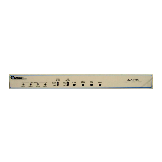
OAC-170D 70 MHZ AMPLIFIER ADJUSTMENT
The OAC-170D Amplifier Adjustment is performed to ensure that the total gain from the
Downconverters to the input of the CS6716 is set for 40db +/- .25db. The OAC-170D
provides the necessary gain between the downconverter outputs and the CS6716 digital
troposcatter modem inputs via four 16db adjustable IF amplifiers.
NOTE: This procedure is not normally required in the field; however, it should be
performed after the replacement of any major equipment in the receive chain. LNA,
downconverter, IF Test Panel and/or any associated cables in the receive path.
STEP 1
Set the CS6716 modem to Default Configuration and place Modem to Online state:
a. On the modem front panel keypad, select ENT for Main Menu then select
ON/OFFLINE, then select OFFLINE to place the modem in the offline state.
b. From the Main Menu select CONFIG, then select DEFAULT to set the modem to
default configuration.
c. From the Main Menu select ON/OFFLINE, and then select ONLINE to place the
modem into the online state.
STEP 2
Remove all of the U links from the IF Data Patch Panel as shown in Fig 1.1.
Figure 1.1
Advertisement
Table of Contents

Related Manuals for Comtech EF Data OAC-170D


Summary of Contents for Comtech EF Data OAC-170D
- Page 1 The OAC-170D Amplifier Adjustment is performed to ensure that the total gain from the Downconverters to the input of the CS6716 is set for 40db +/- .25db. The OAC-170D provides the necessary gain between the downconverter outputs and the CS6716 digital troposcatter modem inputs via four 16db adjustable IF amplifiers.
- Page 2 RSL to display the Receive Signal Level (RSL) for all four receive channels. STEP 6 On the OAC-170D front panel, adjust RCVR-1 potentiometer until a reading of -40 dBm is obtained on the CS6716 modem RSL1 display, refer to Fig 1.3 NOTE: Clockwise (CW) Increases the level.
- Page 3 STEP 7 Repeat steps 4-6 for each corresponding RX IF inputs 2, 3 and 4. Refer to Fig 1.4 and Fig 1.5. TX1 IF to RX2 IF TX1 IF to RX 3 IF TX1 IF to RX 4 IF Figure 1.4 Figure 1.5 STEP 8 Restore equipment to original configuration.
- Page 4 GAIN EQUALIZATION This procedure is performed to equalize the total gain through the receive path to the CS- 6716 modem. Gain Equalization is necessary for the modem to take advantage of the multiple diversity schemes in the various AN/TRC-170 systems STEP 1 For proper Gain Equalization, the system must not be in loop-back and the RX system must be tuned at least 100 MHz away from the XMT frequency.
- Page 5 STEP 5 While observing the RSL levels on the CS6716 Modem front Panel display, adjust RCVR1-RCVR4 potentiometers on the OAC-170D for the lowest common RSL to within +/- 0.25 dB. Refer to fig 1.2 and fig 1.3. NOTE: The lowest RSL is the highest numerical value i.e. -74 is lower than -72.
Need help?
Do you have a question about the OAC-170D and is the answer not in the manual?
Questions and answers