
Subscribe to Our Youtube Channel
Summary of Contents for Pars ABL GIANT 3.0
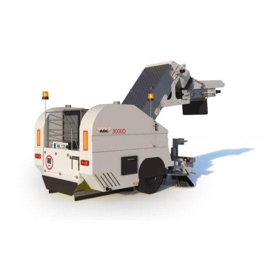
- Page 1 MADE IN SWEDEN ABL GIANT 3.0 MANUAL HEAVY-DUTY MECHANICAL ELEVATOR TRAILER SWEEPING MACHINE ALLOWED FOR 80 KM/H TRANSPORT SPEED www.abl.se Version 01/2020 Copyright © ABL AB Edition original 2020...
- Page 2 Introduction We congratulate to the choice of ABL GIANT 3.0 Sweeping machine The manual book will make you familiar with the machine. The machine has been designed and developed using the latest technology, combined with many years of production experience.
-
Page 3: Table Of Contents
TABLE OF CONTENTS GENERALLY WARRANTY ASSEMBLY DRAWING TOWING VEHICLE SECURITY AND WARNING LABELS POSITIONING OF SAFETY AND WARNINGS LABELS SAFETY 11-14 AFTER FIRST 8 HOUR CONNECTION OF MACHINE BEHIND TRUCK DRIVING FUNCTION 17-19 SWEEPING 20-21 LUBRICATION AND MAINTENANCE 22-39 REPLACEMENT OF WEAR PARTS 40-43 SETTINGS 44-52... -
Page 4: Generally
GENERALLY ABL GIANT 3.0 is a truck towed mechanical elevator sweeper with its own diesel engine for hydraulic operation. This machine has a wheel axle with spring leaf suspension which is specially adapted for this machine, it allows to transport the machine at 80 km/h on the roads. -
Page 5: Warranty
WARANTY ABL provides a 12-month factory warranty on each new machine. Warranty applies to material defects and improper work of up to a maximum of 1000 operating hours and provided that the prescribed service and maintenance has been performed. In the event of a design failure, ABL assumes all costs. Otherwise only incorrect parts and freight are replaced in one direction. -
Page 6: Assembly Drawing
ASSEMBLY DRAWING Main dimension - Front view / Back view... - Page 7 ASSEMBLY DRAWING Main Dimension – Side view / Component view...
-
Page 8: Towing Vehicle
TOWING VEHICLE The vehicle should be a tipping truck and should be equipped with the following Rotating warning lights Adapted towing device Connectors for connecting lighting, brakes, left and right turn indicators Towing bracket When connecting a machine to the truck, the tow bar must be adjusted so that it is horizontal between the truck and the sweeper. -
Page 9: Security And Warning Labels
SECURITY AND WARNING LABELS Warning! Serious person or property damage can be caused if the warning instructions are not followed, always read the instructions manual. Read this manual before using the machine Engine must always be stopped before work Warning rotating brushes Do not stand between Truck and machine Maximum hydraulic pressure 150 Bar... -
Page 10: Positioning Of Safety And Warnings Labels
POSITIONING OF SAFETY AND WARNINGS LABELS... -
Page 11: Safety
SAFETY Safety before starting Read the instructions manual carefully and learn how the sweeper works Read all the warning instructions in this book and learn where they are on machine Make sure everything works on machine While driving Make sure nobody gets too close to the machine during the work Ensure that all safety guards are mounted on the machine When reversing make sure no one is behind or on the sweeper Emergency stop... - Page 12 SAFETY Disconnection of sweeper should be done as below Always apply the sweepers parking brake first (A) Disconnect brake (B), light (C), remote box (D) Disconnect towing eye (E) Support leg down (F) Finally, main circuit switch (G) Important at minus degrees Always empty the water tanks by unscrewing the bottom plug Empty water pump, water filter hoses and nozzles on all water Blow with compressed air until all water Is gone...
- Page 13 SAFETY Loading and fastening When loading a sweeper with a crane, lifting wire must be attached to each side on the elevator in the attachment bracket found on the machine. Lifting wire most also be attached at the rear where the bracket is located. When transporting a sweeper on another vehicle, the machine must be fixed on each side on wheel axle, In the bracket mounted on the chassis.
- Page 14 SAFETY The loads of the towing vehicle Warning the vehicle must be able to handle weights as follows Static pressure vertically 850kg 1s = Service weight 3500kg Total weight 5070kg...
-
Page 15: After First 8 Hour
MACHINE RUN-IN AFTER THE FIRST 8 HOUR IMPORTANT After the first 8 hours this should be tightened Wheel nuts Side brush nuts Hydraulic hoses, Couplings Elevators alu rakes nuts The sweeper must be checked continuously, to ensure that the function is maintained and that any consequentially damage is prevented. -
Page 16: Connection Of Machine Behind Truck
CONNECTION OF MACHINE BEHIND TRUCK CONNECTION Go backward to the sweeper Connect towing eye (A) make sure the machine is horizontal in relation to truck Lower the support leg to the correct height (B) with the button (C) on the electric box Connect all contacts for light (D), brake (E), remote box (F) to the truck Attach both rubber straps (G) to each side of the truck body Release the parking brake (H) -
Page 17: Driving Function
DRIVING FUNCTION ABL ES SWEEP CONTROL Has been developed based on a clear goal, we want to make it easier for the driver to work. All the sweep functions are handled from CAN bus-controlled display, the display should be placed clearly visible and within comfortable distance from driver. BILDER... - Page 18 DRIVING FUNCTION CONTROLCENTER The box is placed on the left side it consists of starter key for diesel engine, main switch, emergency stop, switch for support leg. The battery is protected in the black box for water and dust.
- Page 19 DRIVING FUNCTION CONTROL OF HYDRAULIC VALVES Sweepers hydraulic valves are safely placed under stainless steel box.
-
Page 20: Sweeping
SWEEPING BEFORE SWEEPING Fill the fuel tank with diesel, through the filling tube located on the top of the tank Fill the water tank at the connection on the top right or left water tank Insert the key of the main switch Start the diesel engine, and leave the machine idle for a few minutes to warm up the hydraulic oil Open the water valve... - Page 21 SWEEPING FUNCTION OF ABL ES SWEEP CONTROL...
- Page 22 LUBRICATION AND MAINTENANCE INTERVAL SCHEDULE ALL SERVICES INCLUDES CHECKING FOR OIL LEAKS, AND WORN OR DAMAGED PARTS During all service work with the elevator or when the door is open, no one should be on the sweeper. There is a risk of serious injury to anyone near the elevator when it is rotating.
- Page 23 LUBRICATION AND MAINTENANCE INTERVAL SCHEDULE DAILY WASH After every work session, the sweeper must be cleaned thoroughly. Start the elevator open the door, wash with water in the elevator as it rotates slowly until it becomes completely clean Start the conveyor wash with water in the conveyor as it rotates slowly until it becomes completely clean Open the door to the centre brush, empty the sand box Then wash the entire machine very carefully...
- Page 24 LUBRICATION AND MAINTENANCE INTERVAL SCHEDULE 8 Hours service inspection Check the oil level in the diesel engine Check the fluid level in the engine cooler Check the air filter for the diesel engine Check the hydraulic oil level and the breathing filter Clean the water filter After the first 8 operating hours, following must also be tightened Wheel bolts...
- Page 25 LUBRICATION AND MAINTENANCE INTERVAL SCHEDULE 8 Hours service or if needed after daily inspection These following points should be lubricated Lower elevator shaft (A) right and left bearing Upper elevator shaft (B) right and left bearing Centre brush bearing (C) left side Centre brush bracket (C) right and left side Conveyor drive rollers (D) right and left bearing Side brush sliding axle (E) right and left side...
- Page 26 LUBRICATION MAINTENANCE INTERVAL SCHEDULE 8 Hours service water filter and water nozzles Unscrew the filter bowl (A) and the filter element (B) clean it in clean water Remove water nozzles, disassemble strainer and nozzle (C) clean it in clean water 8 Hours service should return at 8 hours interval...
- Page 27 LUBRICATION MAINTENANCE INTERVAL SCHEDULE Industrial Engine The engine maintenance section in this book is a guide to engine care, recommended service should be performed at the appropriate intervals as indicated in the maintenance interval schedule For more detailed engine service, check out the engine Operation and Maintenance manual that comes with each new machine.
- Page 28 LUBRICATION MAINTENANCE INTERVAL SCHEDULE DIESEL ENGINE MAINTENANCE AFTER FIRST 50 HOUR THIS PROCEDURE SHOULD BE DONE EVERY 500 HOURS INTERVAL Replace oil and oil filter Remove motor hood Place a bucket under the drain plug (1) Warm up the engine 10 minutes so that the engine oil gets hot before changing the oil filter Turn off the engine, turn of the main switch Remove the drain plug (1) in the oil pan (3), drain engine from oil...
- Page 29 LUBRICATION AND MAINTENANCE INTERVAL SCHEDULE DIESEL ENGINE MAINTENANCE EVERY 500 HOURS Replace of primary Fuel filter with water separator with manual priming pump Place a suitable container under the water separator to catch any fuel that might spill. Clean-up any spilled fuel. Clean the outside body of the filter assembly Install a suitable tube onto drain (2) open the drain valve (1) rotate the drain valve fully counter clockwise.
- Page 30 LUBRICATION AND MAINTENANCE INTERVAL SCHEDULE DIESEL ENGINE MAINTENANCE Air Cleaners replacement and air precleaner check Ensure that the outer body of the air cleaner to be serviced is clean and free from dirt Inspect the top cover (1) and if necessary, remove top cover to clean cover Ensure that dirt cannot enter the air cleaner system with top cover removed.
- Page 31 LUBRICATION AND MAINTENANCE INTERVAL SCHEDULE DIESEL ENGINE MAINTENANCE RECORDS ABL recommends the retention of accurate maintenance records. Maintenance records are a key element of a maintenance program that is managed. Accurate maintenance can help you and your ABL dealer to fine-tune the recommended maintenance intervals, in order to meet the specific operating situation.
- Page 32 LUBRICATION MAINTENANCE INTERVAL SCHEDULE HYDRAULIC PRESSURE FILTER MAINTENANCE AFTER FIRST 50 HOUR Replacement of hydraulic filter Unscrew the filter bowl (A) Replace filter elements (B) Reinstall the filter bowl (A) To avoid burning your hands, do not do this while the hydraulic oil is hot...
- Page 33 LUBRICATION MAINTENANCE INTERVAL SCHEDULE HYDRAULIC PRESSURE FILTER MAINTENANCE 500 HOUR Replacement of hydraulic filter and Breathing filter Unscrew the filter bowl (A) Replace filter elements (B) Reinstall the filter bowl (A) Replace breathing filter (C) To avoid burning your hands, do not do this while the hydraulic oil is hot 500 hours of service should return at intervals of 500 hours...
- Page 34 LUBRICATION AND MAINTENANCE INTERVAL SCHEDULE EVERY 1000 HOURS OR 2 YEARS REPLACE HYDRAULIC OIL AND PRESSURE FILTER Let the sweeper work until the hydraulic oil is little warm Turn off the machine, turn off the main power switch Unscrew the bottom plug (A) from the hydraulic tank and drain the oil Loosen the lid (B) and clean the tank internally Clean and install the bottom plug (A) Replace the breathing filter (C)
-
Page 35: Lubrication And Maintenance
LUBRICATION AND MAINTENANCE WORK WHEEL AXLE To maintain vehicle operation and road safety, maintenance work shall be performed at the specified intervals. For more detailed wheel axle service, check out the wheel axle workshop manual that comes with each new machine. Control and adjustment of wheel bearing play at every brake lining replacement latest annually Lift the wheel off the ground... - Page 36 LUBRICATION AND MAINTENANCE WORK PNEUMATIC BRAKES The braking force is regulated by the trucks brake pedal, the brake cylinders and the brake arms are adjustable to provide adequate braking without the wheels locking The spring brake cylinder has a diaphragm cylinder (A) for braking and a spring brake section (B) for emergency brake / parking brake Before using machine, check that the screws (G) are fully screwed in, to enable the emergency brake to take effect...
- Page 37 LUBRICATION AND MAINTENANCE WORK EMERGENCY AND PARKING BRAKE Pneumatic brakes have an emergency brake / Parking brake, that automatically goes in and brake the wheels when the air pressure from the truck is released. If the machine must be parked on or near public roads, the machine must also be secured with brake pads. In the case of long-term parking, the parking brake should be switched off by pressing the valve (1) instead the machine should be secured with brake pads.
- Page 38 LUBRICATION AND MAINTENANCE WORK BRAKE MAINTENANCE Drain condensation water from the air tank daily, before running. And if necessary, by pressing the drain valve (1) on the bottom of the tank when the tank is pressurized 1-2 times per season or if the breaking action is delayed, remove and clean the line filters (2)
- Page 39 LUBRICATION AND MAINTENANCE WORK BRAKE SCHEDULE...
-
Page 40: Replacement Of Wear Parts
SIDE BRUSH REPLACEMENT OF SIDE BRUSH Brushes should be replaced before ever they wear out completely. Once the length of brush has shortened to below its half original length the sweep becomes inefficient, ineffective and therefore costly. From then on dirt and debris will be spread over the road surface rather than swept and deposited properly to elevator Sweeper is equipped with two brushes with wooden frame, consisting of three rows of brush. - Page 41 CENTRE BRUSH REPLACEMENT OF CENTRE BRUSH Brushes should be replaced before ever they wear out completely. Once the length of brush has shortened to below its half original length the sweep becomes inefficient, ineffective and therefore costly. From then on dirt and debris will be spread over the road surface rather than swept and deposited properly to elevator Sweeper is equipped with one complete roller brush with core of plastic, brush material can be in poly, steel or mixed poly/steel...
- Page 42 COLLECTOR SHOES REPLACEMENT OF COLLECTOR SHOES RUBBER Collector shoes prevent the stones from falling out on the side of the centre brush and prevent getting stripes behind the machine. Therefore, is it important that the rubber on the shoes lie against the ground, and that the shoes seal against the centre brush on both sides of centre brush.
- Page 43 ELEVATOR RUBBER / ALU RAKE PROFILE REPLACEMENT OF RUBBER/RAKE PROFILE If the elevator wants to be able to transport all gravel and debris to the conveyor, it is necessary that the rubber and the rake profile in elevator are not broken. There is a total of 20 pcs.
-
Page 44: Settings
SETTINGS SIDE BRUSH SETTINGS The right angle and tilting of the side brushes is necessary for a sweeper to produce a good result, if the side brush has a small angle, it will throw the trash back to the curb stone. If the side brushes have too much contact angle, it will leave stripe at the curb stone. - Page 45 SETTINGS ANGLE SETTINGS OF SIDE BRUSH To adjust the side angle, loosen both nuts (A) tilt the bracket 5-10 degrees To adjust the tilting angle, loosen both nuts (B) tilt the bracket forward or backward to adjust the tilt angle...
- Page 46 SETTINGS SIDE BRUSH PRESSURE Side brush is equipped with ABL automatic brush floating system, cylinder (A) control the brush pressure, which means that the side brush always has the right brush pressure against the ground. Regardless of the wear of the brush, it automatically follows the bumps in the ground.
- Page 47 SETTINGS CENTRE BRUSH PRESSURE Centre brush is equipped with ABL automatic brush floating system, both cylinders (A) control the brush pressure, which means that the centre brush always has the right brush pressure against the ground. Regardless of the wear of the brush, it automatically follows the bumps in the ground.
- Page 48 SETTINGS SETTING OF SWEEPING WIDTH Sweep width can be hydraulically adjusted there is a cylinder (A) on each side brush that adjusts the sweep width Increase sweep cylinder (A) moves out Decrease sweep cylinder (A) moves in When sweeping, especially in curves sweepers may leave stripes. If this occurs, the sweep width must be reduced cylinders (A) moves in...
- Page 49 SETTINGS ADJUSTMENT OF ELEVATOR BELT Proper tension of elevator belt is necessary to get a long service life Loosen the four nuts (A) on each side Loosen the nut (B) on each side Tighten the belts by adjusting nut (C) equally on both side The belt tension is ok when the alu rake (C) can be moved about 50 mm down the middle of the elevator Tighten the nuts (B), (C) again on both side...
- Page 50 SETTINGS ADJUSTMENT OF CONVEYOR BELT Proper tension of conveyor belt is necessary to get long service life, it is important that the belt runs in the middle of the rollers. Adjustment is made as follows Start the conveyor Stand on a ladder or the truck platform Loosen the four bolts (A) on each side Loosen the nut (B) on each side Adjust the nuts (C) on each side until the belt is the centre of the rollers...
- Page 51 SETTINGS ADJUSTMENT OF STRING COLLECTOR RUBBER String collector rubber prevents stones from being swept to other side brushes, it places the dirt along a string between the brushes. The rubber is adjusted by loosening the bolt (A) adjust the rubber so it hangs 5 mm from ground...
- Page 52 MACHINE STORAGE DO THIS BEFORE STORING THE MACHINE FOR A LONGER TIME Wash machine thoroughly If possible, remove all brushes from machine. Then you avoid that the brushes are not destroyed by their own weight against the ground Empty water tank, water filter, water pump, hoses and nozzles from water Lubricate all grease nipples, and check oil leaks and replace worn or damaged parts if necessary Switch off parking brake...
-
Page 53: Troubleshooting
TROUBLESHOOTING The troubleshooting section in this book is a guide, do not hesitate to contact your ABL service partner if you need assistance ERROR DESCRIPTION PROBABLE CAUSE SOLUTION Low oil level Add hydraulic oil Hydraulic Component failure Replace the component High hydraulic oil temp Clogged hydraulic filter Change filter... -
Page 54: Technical Information
TECHNICAL INFORMATION Chassis Built by steel profiles Inner core centre brush Welded steel Weight Ca.3500 kg service weight total 5070 kg Brush material Plastic/steel or steel/plastic mixed Sweeping width 2500-3000mm Diameter centre brush 750mm Hydraulic pump Gear pump 60 l/min max pressure 150 Width centre brush 1016mm Hydraulic motors... - Page 55 TECHNICAL INORMATION HYDRAULIC CIRCUIT...
- Page 56 TECHNICAL INFORMATION ELECTRIC CIRCUIT...
-
Page 57: Ec Declaration
Authorized person to complete this technical documentation Name: Richard Liljedahl, Support & Construction Manufacturer Machines Product: Towed elevator sweeping machine Type: ABL GIANT 3.0 Serial Number: ………………………………………………… We, as manufacturer ensure that the machine covered by this declaration complies with all applicable provisions of directives...
Need help?
Do you have a question about the ABL GIANT 3.0 and is the answer not in the manual?
Questions and answers