
Related Manuals for Viewpro Q10N


Summary of Contents for Viewpro Q10N
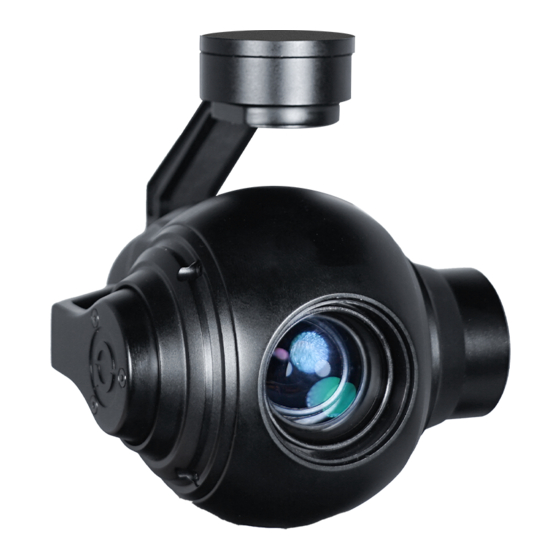
- Page 1 Q10N 10x Optical Zoom Gimbal Camera User Manual Standard Version Viewport Version 标准版 快拆版 For more details please scan the QR code or visit our website: www.viewprotech.com...
-
Page 2: Disclaimer And Warning
Important Note 1.Product Introduction 1.1 Introduction Q10N is a high-precision 3-axis gimbal integrated with a 10x optical zoom, powered by 1/3 SENSOR CMOS module, approx.2.48 million effective pixels, built in encoder with IP output only. It supports visible optical zoom, photographing and video. The OSD can display the yaw/pitch angle and zoom times. -
Page 3: Standard Version
1.2 In the Box A. Standard Version Gimbal Camera USB to TTL Cable x 1 pc x 1 pc Copper Cylinder M3 Screw x 4 pcs x 8 pcs Power Cable x 1 pc B. Viewport Version Gimbal Camera USB to TTL Cable x 1 pc x 1 pc Copper Cylinder... -
Page 4: Installation Instruction
TTL / S.BUS Control Cable x 1 pc TTL Connect Cable x 3 pcs Ethernet Cable x 1 pc 2. Installation Instruction 2.1 Overview [10] [11] [12] Control Box Back Side (Standard Version) [10] [12] [11] Viewport (Viewport Version) - Page 5 [1] Control box [7] TF card slot [2] Upper damping board [8] Roll axis motor [3] Lower damping board [9] Pitch axis motor [4] FHD zoom camera [10] 3-6S power interface [11] Ethernet interface [5] Damping ball [6] Yaw axis motor [12] Viewport unlock button Please ensure that there isn’t any obstacle while the motor rotating.
- Page 6 2.2.2 Control Box Printing (Viewport Version) Front Side POWER Left Side ETHERNET UART & S.BUS Right Side...
- Page 7 2.3 Device Dimensions (Standard Version) Unit: mm 111.4 91.6...
- Page 8 2.3 Device Dimensions (Viewport Version) Unit: mm Control Box 91.6 111.4...
- Page 9 2.4 Install Mounting Part (1) Find out the arrow on the gimbal which indicating the yaw heading of the payload (i.e. the lens direction when the camera power on), and synchronize with the direction specified by the UAV. (2) Fix one end of the copper cylinder on the screw hole of lower damping board, and use M3 screw to fasten it.
- Page 10 2.5 Viewport Release Instruction × 1. Make sure the two white stripes indicated in above picture are aligned with each other. (If the stripes are not aligned to each other, please pinch the connector part and turn it to left manually)
- Page 11 2. Align the white dot (unlock icon) to the red triangle (below unlock button), push the gimbal into the Viewport completely and then rotate the gimbal camera anticlockwise. 3. When you hear "click" sound (when red dot is aligned to the red triangle) means the gimbal camera and Viewport has been locked.
- Page 12 2.6 Install TF Card TF (Micro SD card): Install the TF card to the card slot (Re. 2.1 Overview). Support max 128GB. Request Class 10 (10m/s) transmis- sion speed or higher and FAT32 or exFAT format. Make sure device is power off when inserting the TF card, hot plugging is not supported.
-
Page 13: Signal Control
When using user interface software Viewlink for network connection, the network of external device (computer) should be the IP address: 192.168.1.2 (choose the last byte among 2~254, can not be 160 same as the gimbal), subnet mask: 255.255.255.0, Default gateway: 192.168.1.1, and all firewalls of the computer must be closed. - Page 14 PWM IN 5V OUTPUT Remote Controller Receiver Connection Diagram (Standard Version) Receiver Remote Controller Connection Diagram (Viewport Version)
- Page 15 3.1.2 PWM Control Operation Instruction 1) Pitch (PWM Pitch channel in to control Pitch. Joystick, rotary knob or 3-gear switch on remote control are optional. 3-gear switch as example.) Position 1 Position 2 Position 3 Low Gear Middle Gear High Gear Pitch Up Pitch Stop Pitch Down...
- Page 16 Position 1 Position 2 Position 3 Low Gear Middle Gear High Gear Position 1: Low speed mode, control pitch / yaw with this mode at lowest speed Position 2: Middle speed mode, control pitch / yaw with this mode at middle speed Position 3: High speed mode, control pitch / yaw with this mode at highest speed...
- Page 17 5) Zoom (PWM Zoom channel in to control Zoom. Joystick, rotary knob or 3-gear switch on remote control are optional. 3-gear switch as example.) Position 1 Position 2 Position 3 Low Gear Middle Gear High Gear Zoom Out Stop Zoom Zoom In 6) Focus ( not functional for this channel) 7) Pic/Rec (PWM Pic/Rec channel in to control take picture and...
- Page 18 8) Multi: Backup channel Position 1 Position 2 Position 3 Low Gear Middle Gear High Gear 3.2 Serial Port / TTL Control TTL communication requirements: TTL signal is 3.3V, baud rate: 115200, data bit 8, stop bit 1, no parity, HEX send and receive. Connection Diagram (PC - USB to TTL Cable- Gimbal Camera as example): Gimbal Camera...
- Page 19 TTL control protocol file. ViewLink is a user interface developed by Viewpro for Viewpro gimbal cameras, you can download it from Viewpro website (www.viewpro- tech.com) or ask distributors for installation package.
-
Page 20: S.bus Control
3.3 S.BUS Control Control the gimbal camera functions by one combining signals. Connect the external S.Bus to S.Bus port on the control box, and the external S.bus signal GND connect to the GND interface of the control box. Wiring Diagram (Take Futaba remote control for example): 5V OUTPUT Remote Control Receiver... - Page 21 Receiver Remote Control Wiring Diagram Viewport Version S.Bus control mode: default S.Bus signal channel 9-15 to control gimbal camera functions (the function of channel is consistent with corresponding channel in PWM function description) Channel 9: Yaw Control Channel 10: Pitch Control Channel 11: Mode Control Channel 12: Zoom Control Channel 13: Focus Control...
- Page 22 (please contact with our technical support for the setting instruction.) 3.4 TCP control For Viewpro gimbal cameras with Ethernet output, the default IP address is: 192.168.1.160, control port: 2000. You can send the corresponding protocol to realize TCP control after connecting.
-
Page 23: Specification
4. Specification Hardware Parameter Working voltage Input voltage 3S ~ 6S Output voltage 5V (connect with PWM) Dynamic current 450~700mA @ 12V Idle current 450mA @ 12V Working environment -20℃ ~ +60℃ temp Output IP (720p/1080P 25/30fps) Local-storage SD card (Up to 128G,class 10, FAT32) Photo storage format JPG (1920*1080/1280*720) Video storage format... - Page 24 One-key to center √ Camera spec Imager Sensor 1/3" Panasonic CMOS Sensor Total pixel 2.48M Picture quality Full HD 1080 (1920*1080) Optical zoom 10x, f = 5.1mm ~ 51mm Digital zoom D: 68°(Wide end) ~ 6.7° (Tele end) Angle of View H: 54°(wide end) ~ 4.9°(tele end) (D, H, V) V: 31°(wide end) ~ 4.0°(tele end)
- Page 25 Mode / AGC / Shut Speed / Iris / DSS / Exposure Flickerless / Brightness / WDR/BLC / D&N Defog Packing Information N.W. 473g / 538g (Viewport version) 91.6*111.4*143.1mm (including control box)/ Product meas. 91.6*111.4*148.8mm(Viewport Version) 1pc gimbal camera device, screws, USB to Accessories TTL cable / Hight quality box with foam cushion...
- Page 26 5. FAQ 1. 1.How to modify the IP address of Q10N? A: Enter “192.168.1.168” at IE web, and go into the IP CAMERA interface -- download the activeX control and login the control as an administrator. Username: admin, Password: 123456, and click the “system setup”...
Need help?
Do you have a question about the Q10N and is the answer not in the manual?
Questions and answers