
Subscribe to Our Youtube Channel
Related Manuals for Viewpro Q20KTIR


Summary of Contents for Viewpro Q20KTIR
- Page 1 Q20KTIR 20x 4K EO + IR Dual-Sensor Object Tracking Gimbal Camera User Manual User Manual Standard Version Viewport Version 标准版 快拆版 For more details please scan the QR code or visit our website: www.viewprotech.com...
-
Page 2: Disclaimer And Warning
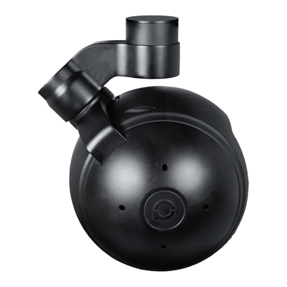
The 3 axis gimbal can achieve stabilization in yaw, roll and pitch. The integrated design of damping system and gimbal can greatly reduce mechanical vibration. Q20KTIR is widely used in UAV industries of public security, electric power, fire fighting, zoom aerial photography and other industrial applications. -
Page 3: Standard Version
1.2 In the Box A. Standard Version Gimbal Camera USB to TTL Cable x 1 pc x 1 pc Copper Cylinder M3 Screw x 4 pcs x 8 pcs Power Cable x 1 pc B. Viewport Version Gimbal Camera USB to TTL Cable x 1 pc x 1 pc Copper Cylinder... -
Page 4: Installation Instruction
TTL / S.BUS Control Cable x 1 pc TTL Connect Cable x 3 pcs Ethernet Cable x 1 pc 2. Installation Instruction 2.1 Overview [11] [13] [12] [10] Control Box Back Side (Standard Version) [11] [14] [13] Viewport [12] (Viewport Version) - Page 5 [8] TF card slot [1] Control box [2] Upper damping board [9] Roll axis motor [3] Lower damping board [10] Pitch axis motor [4] FHD zoom camera [11] 3-6S power interface [5] Infrared thermal camera [12] Micro HDMI interface [6] Damping ball [13] Ethernet interface [7] Yaw axis motor [14] Viewport unlock button...
- Page 6 2.2.2 Control Box Printing (Viewport Version) Front Side POWER Left Side ETHERNET UART & S.BUS Right Side...
- Page 7 2.3 Device Dimensions (Standard Version) Unit: mm 107.0 62.2 31.5 13.0 107.0 132.3 118.7...
- Page 8 2.3 Device Dimensions (Viewport Version) Unit: mm 99.9 Control Box 78.0 100.0 100.0 132.3 118.7...
- Page 9 2.4 Install Mounting Part (1) Find out the arrow on the gimbal which indicating the yaw heading of the payload (i.e. the lens direction when the camera power on), and synchronize with the direction specified by the UAV. (2) Fix one end of the copper cylinder on the screw hole of lower damping board, and use M3 screw to fasten it.
- Page 10 2.5 Viewport Release Instruction × 1. Make sure the two white stripes indicated in above picture are aligned with each other. (If the stripes are not aligned to each other, please pinch the connector part and turn it to left manually)
- Page 11 2. Align the white dot (unlock icon) to the red triangle (below unlock button), push the gimbal into the Viewport completely and then rotate the gimbal camera anticlockwise. 3. When you hear "click" sound (when red dot is aligned to the red triangle) means the gimbal camera and Viewport has been locked.
- Page 12 2.6 Install TF Card TF (Micro SD card): Install the TF card to the card slot (Re. 2.1 Overview). Support max 128GB. Request Class 10 (10m/s) transmis- sion speed or higher and FAT32 or exFAT format. Make sure device is power off when inserting the TF card, hot plugging is not supported.
-
Page 13: Signal Control
Above output mode is optional, HDMI and SDI output cannot coexist at the same time. Please subject to your actual product. When using user interface software Viewlink for network connection, the network of external device (computer) should be the IP address: 192.168.2.2 (choose the last byte among 2~254, can not be 119 same as the gimbal), subnet mask: 255.255.255.0, Default gateway: 192.168.2.1, and all firewalls of the... - Page 14 PWM IN 5V OUTPUT Remote Controller Receiver Connection Diagram (Standard Version) Receiver Remote Controller Connection Diagram (Viewport Version)
- Page 15 3.1.2 PWM Control Operation Instruction 1) Pitch (PWM Pitch channel in to control Pitch. Joystick, rotary knob or 3-gear switch on remote control are optional. 3-gear switch as example.) Position 1 Position 2 Position 3 Low Gear Middle Gear High Gear Pitch Up Pitch Stop Pitch Down...
- Page 16 Position 1 Position 2 Position 3 Low Gear Middle Gear High Gear Position 1: Low speed mode, control pitch / yaw with this mode at lowest speed Position 2: Middle speed mode, control pitch / yaw with this mode at middle speed Position 3: High speed mode, control pitch / yaw with this mode at highest speed...
- Page 17 4) Zoom (PWM Zoom channel in to control Zoom. Joystick, rotary knob or 3-gear switch on remote control are optional. 3-gear switch as example.) Position 1 Position 2 Position 3 Low Gear Middle Gear High Gear Zoom Out Stop Zoom Zoom In 5) Focus (PWM Focus channel is to control PIP / IR color palette switch.
- Page 18 Position 1 Position 2 Position 3 Low Gear Middle Gear High Gear Switch from Position 2 to 1: Take a picture OSD display 'REC IMG' a second. Switch from Position 2 to 3: Start record / repeat operation to stop record Start record, the OSD display rec hh:mm:ss.
- Page 19 3.2 Serial Port / TTL Control TTL communication requirements: TTL signal is 3.3V, baud rate: 115200, data bit 8, stop bit 1, no parity, HEX send and receive. Connection Diagram (PC - USB to TTL Cable- Gimbal Camera as example): Gimbal Camera Cable RX (White)
-
Page 20: S.bus Control
TTL control protocol file. ViewLink is a user interface developed by Viewpro for Viewpro gimbal cameras, you can download it from Viewpro website (www.viewpro- tech.com) or ask distributors for installation package. - Page 21 5V OUTPUT Remote Control Receiver Wiring Diagram Standard Version Receiver Remote Control Wiring Diagram Viewport Version...
- Page 22 S.Bus control mode: default S.Bus signal channel 9-15 to control gimbal camera functions (the function of channel is consistent with corresponding channel in PWM function description) Channel 9: Yaw Control Channel 10: Pitch Control Channel 11: Mode Control Channel 12: Zoom Control Channel 13: Focus Control Channel 14: Pic/Rec Control Channel 15: Multi Backup...
-
Page 23: Specification
4. Specification Hardware Parameter Working voltage Input voltage 3S ~ 6S Output voltage 5V (connect with PWM) Dynamic current 950~1350mA @ 12V Idle current 950mA @ 12V Working environment -20℃ ~ +60℃ temp micro HDMI(1080P25/30fps)/IP (4K/1080p Output 25/30fps ) SD card (Up to 128G,class 10, FAT32 or ex Local-storage FAT format) Photo storage format... - Page 24 Pitch/Tilt: -35°~90°, Controllable Range Yaw/Pan: ±290° / ±360°*N (IP output version) Vibration angle Pitch/Roll: ±0.02°, Yaw:±0.02° One-key to center √ EO Camera Spec Imager Sensor SONY 1/2.5" "Exmor R" CMOS Total pixel 8.51MP 20x, F2.0 to F3.8,f = 4.4 mm (Wide), 88.4 mm Optical zoom (Tele) Digital zoom...
- Page 25 Back light On/Off compensation Gain Auto White balance Auto/Manual Electronic shutter 1/1 to 1/10000 sec. (22 steps) speed Noise reduction On/Off (level 5 to 1/ Off, 6 steps) Defog mode On/Off (Low, Mid, High) Focus Auto/Manual/One-time automatic focus Focus speed Lens initialization Built-in User presetting bit...
- Page 26 Recognize Distance 184 meters (Man: 1.8x0.5m) Verified Distance 92 meters (Man: 1.8x0.5m) Detective Distance 2255 meters (Car: 4.2x1.8m) Recognize Distance 564 meters (Car: 4.2x1.8m) Verified Distance 282 meters (Car: 4.2x1.8m) Uncooled long wave (8μm~14μm) thermal Working mode imager Detector pixel 640*480 Pixel size 17μm...
- Page 27 Sync correct time Temperature bar (psudo color display) max Thermometry type temp, min temp, FOV center temp (Optional) Temperature warning 0℃~120℃ (For thermometry version only) IR / EO Camera Object Tracking Update rate of 50Hz deviation pixel Output delay of deviation pixel Minimum object contrast...
- Page 28 G.W. 3225g Package meas. 350*300*250mm 5. FAQ 1. How to deal with whitening visible image of Q20KTIR in foggy weather? A: Enable defogging mode. 2. Does Q20KTIR support taking photos during recording? A: Yes. 3. How to set the video storage format of Q20KTIR? A: When the IP output resolution is set to 1920*1080, the storage resolution is 3840*2160;...
Need help?
Do you have a question about the Q20KTIR and is the answer not in the manual?
Questions and answers