
Related Manuals for Viewpro Z40TIR


Summary of Contents for Viewpro Z40TIR
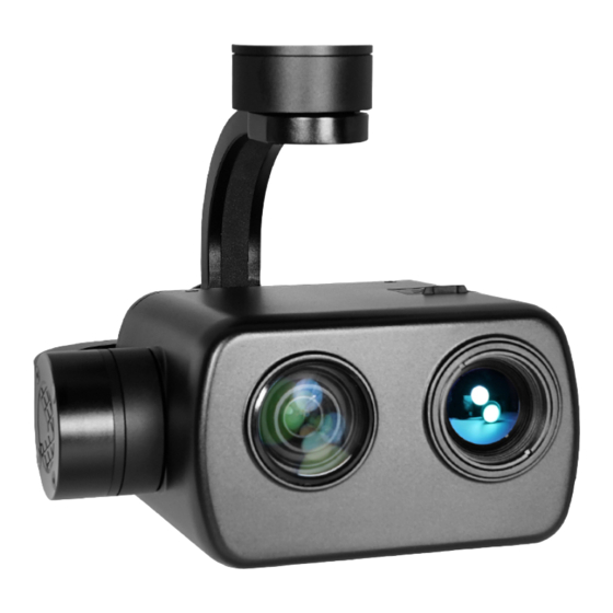
- Page 1 Z40TIR 40x 4K EO + IR Dual-Sensor Object Tracking Gimbal Camera User Manual User Manual Standard Version Viewport Version 标准版 快拆版 For more details please scan the QR code or visit our website: www.viewprotech.com...
-
Page 2: Disclaimer And Warning
When the external GPS and time input, the OSD can display angle, zoom times, photographing and video status and tracking frame, also can select to turn off the OSD. Z40TIR has geotagging function. GPS coordinate and shooting time can be saved in image file, OSD can display GPS and real-time as well. -
Page 3: Standard Version
Z40TIR is widely used in inspection, surveillance, search and rescue, and other industrial applications. 1.2 In the Box A. Standard Version Gimbal Camera USB to TTL Cable x 1 pc x 1 pc Copper Cylinder M3 Screw x 4 pcs... -
Page 4: Installation Instruction
TTL / S.BUS Control Cable x 1 pc TTL Connect Cable x 3 pcs Ethernet Cable x 1 pc 2. Installation Instruction 2.1 Overview [11] [13] [12] Control Box Back Side [10] (Standard Version) [11] [14] [13] Viewport [12] (Viewport Version) - Page 5 [8] TF card slot [1] Control box [2] Upper damping board [9] Roll axis motor [3] Lower damping board [10] Pitch axis motor [4] FHD zoom camera [11] 3-6S power interface [5] Infrared thermal camera [12] Micro HDMI interface [6] Damping ball [13] Ethernet interface [7] Yaw axis motor [14] Viewport unlock button...
- Page 6 2.2.2 Control Box Printing (Viewport Version) Front Side POWER Left Side ETHERNET UART & S.BUS Right Side...
- Page 7 2.3 Device Dimensions (Standard Version) Unit: mm 62.2 150.1 152.65...
- Page 8 2.3 Device Dimensions (Viewport Version) Unit: mm 41.6 Control Box 154.8 150.1...
- Page 9 2.4 Install Mounting Part (1) Find out the arrow on the gimbal which indicating the yaw heading of the payload (i.e. the lens direction when the camera power on), and synchronize with the direction specified by the UAV. (2) Fix one end of the copper cylinder on the screw hole of lower damping board, and use M3 screw to fasten it.
- Page 10 2.5 Viewport Release Instruction × 1. Make sure the two white stripes indicated in above picture are aligned with each other. (If the stripes are not aligned to each other, please pinch the connector part and turn it to left manually)
- Page 11 2. Align the white dot (unlock icon) to the red triangle (below unlock button), push the gimbal into the Viewport completely and then rotate the gimbal camera anticlockwise. 3. When you hear "click" sound (when red dot is aligned to the red triangle) means the gimbal camera and Viewport has been locked.
- Page 12 2.6 Install TF Card TF (Micro SD card): Install the TF card to the card slot (Re. 2.1 Overview). Support max 128GB. Request Class 10 (10m/s) transmis- sion speed or higher and FAT32 or exFAT format. Make sure device is power off when inserting the TF card, hot plugging is not supported.
-
Page 13: Signal Control
Above output mode is optional, HDMI and SDI output cannot coexist at the same time. Please subject to your actual product. When using user interface software Viewlink for network connection, the network of external device (computer) should be the IP address: 192.168.2.2 (choose the last byte among 2~254, can not be 119 same as the gimbal), subnet mask: 255.255.255.0, Default gateway: 192.168.2.1, and all firewalls of the... - Page 14 PWM IN 5V OUTPUT Remote Controller Receiver Connection Diagram (Standard Version) Receiver Remote Controller Connection Diagram (Viewport Version)
- Page 15 3.1.2 PWM Control Operation Instruction 1) Pitch (PWM Pitch channel in to control Pitch. Joystick, rotary knob or 3-gear switch on remote control are optional. 3-gear switch as example.) Position 1 Position 2 Position 3 Low Gear Middle Gear High Gear Pitch Up Pitch Stop Pitch Down...
- Page 16 Position 1 Position 2 Position 3 Low Gear Middle Gear High Gear Position 1: Low speed mode, control pitch / yaw with this mode at lowest speed Position 2: Middle speed mode, control pitch / yaw with this mode at middle speed Position 3: High speed mode, control pitch / yaw with this mode at highest speed...
- Page 17 5) Zoom (PWM Zoom channel in to control Zoom. Joystick, rotary knob or 3-gear switch on remote control are optional. 3-gear switch as example.) Position 1 Position 2 Position 3 Low Gear Middle Gear High Gear Zoom Out Stop Zoom Zoom In 6) Focus (PWM Focus channel is to control PIP, IR color palette switch, 3-gear switch as example.)
- Page 18 Position 1 Position 2 Position 3 Low Gear Middle Gear High Gear Switch from Position 2 to 1: Take a picture OSD display 'REC IMG' a second. Switch from Position 2 to 3: Start record / repeat operation to stop record Start record, the OSD display rec hh:mm:ss.
- Page 19 3.2 Serial Port / TTL Control TTL communication requirements: TTL signal is 3.3V, baud rate: 115200, data bit 8, stop bit 1, no parity, HEX send and receive. Connection Diagram (PC - USB to TTL Cable- Gimbal Camera as example): Gimbal Camera Cable RX (White)
-
Page 20: S.bus Control
TTL control protocol file. ViewLink is a user interface developed by Viewpro for Viewpro gimbal cameras, you can download it from Viewpro website (www.viewpro- tech.com) or ask distributors for installation package. - Page 21 5V OUTPUT Remote Control Receiver Wiring Diagram Standard Version Receiver Remote Control Wiring Diagram Viewport Version...
- Page 22 (please contact with our technical support for the setting instruction.) 3.4 TCP control For Viewpro gimbal cameras with Ethernet output, the default IP address is: 192.168.2.119, control port: 2000. You can send the corresponding protocol to realize TCP control after connecting.
-
Page 23: Specification
4. Specification Hardware Parameter Working voltage 12V ~ 16V Input voltage 3S ~ 6S Output voltage 5V (connect with PWM) Dynamic current 500mA @ 12V Idle current 400mA @ 12V Power consumption ≤ 6W Working environment -20℃ ~ +60℃ temp Output micro HDMI(HD output 1080P 60fps) / IP SD card (Up to 128G, class 10, FAT32 or... - Page 24 Camera spec Imager Sensor Panasonic 1/2.3inch CMOS Lens F1.8~F3.6(f=4.08~81.6mm) Optical zoom:20x, iA zoom:25x(4k) / 40x Zoom (FHD) Total pixel 25.9MP Record effective pixel 4k:8.29MP / FHD:6.10MP(16:9) Picture effective pixel 25.9MP(4:3) Optical Image 5 axis Optical Image Stabilization Stabilization Record format MPEG-4 4k:3840*2160/30p FHD:1080/60p Record pixel...
- Page 25 Sync system Progressive scanning Local video 1080P 30fps local TF card HD output 1080P/720/480P 60fps HDMI1.4 S/N ratio 38dB Min illumination Color 0.05lux@F1.6 Backlight Backlight compensation/strong light inhibition compensation Gain Auto White balance Auto/Manual Control system UART/IR/PWM Communication PELCO-D, Hitachi protocol or VISCA protocol Focus Auto/Manual/One-time automatic focus...
- Page 26 Output delay of <15ms deviation pixel Minimum object contrast Minimum object size 32*32 pixel Maximum object size 128*128 pixel Tracking speed ±48 ~ ±192 pixel/frame The mean square root values of pulse < 0.5 pixel noise in the object position Thermal Imager Spec Lens size 25mm...
- Page 27 Detective Distance 2255 meters (Car: 4.2x1.8m) Recognize Distance 564 meters (Car: 4.2x1.8m) Verified Distance 282 meters (Car: 4.2x1.8m) Uncooled long wave (8μm~14μm) thermal Working mode imager Detector pixel 640*480 Pixel size 17μm Focusing method Athermal prime lens Emissivity correction 0.01~1 NETD ≤50mK (@25℃) MRTD...
- Page 28 Thermal Object Tracking Update rate of 25Hz deviation pixel Output delay of <3ms deviation pixel Minimum object size 32*32 pixel Maximum object size 128*128 pixel Tracking speed ±48 ~ ±192 pixel/frame Object memory time 100 frames (4s) Packing Information N.W. 945g Product meas.
- Page 29 A: Output is not 4K, Video storage supports 4K. 5. What tools can be used for the network configuration of Z40TIR? A: It can use Viewlink app or Camera Configure Tool. 6. What tools can be used for the EO camera debugging of Z40TIR? A: 4K_Camera_APP_V1.5...
Need help?
Do you have a question about the Z40TIR and is the answer not in the manual?
Questions and answers