Table of Contents

Related Manuals for Viewpro Q10TRIM


Summary of Contents for Viewpro Q10TRIM
- Page 1 Q10TRIM 10x Optical Zoom EO + IR Dual-Sensor Laser Rangefinder Object Tracking Gimbal Camera User Manual User Manual Standard Version Viewport Version 标准版 快拆版 For more details please scan the QR code or visit our website: www.viewprotech.com...
-
Page 2: Disclaimer And Warning
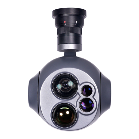
Important Note 1.Product Introduction 1.1 Introduction Q10TRIM is a powerful 3-axis gimbal integrated with a 10x optical zoom camera, a 25mm lens 640*480 IR thermal sensor and a 3km laser rangefinder. It supports visible optical zoom, IR thermal and visible PIP switch, IR color palette switch, photographing and video, target tracking, thermal digital zoom. -
Page 3: Standard Version
1.2 In the Box A. Standard Version Gimbal Camera USB to TTL Cable x 1 pc x 1 pc Copper Cylinder M3 Screw x 4 pcs x 8 pcs Power Cable x 1 pc B. Viewport Version Gimbal Camera USB to TTL Cable x 1 pc x 1 pc Copper Cylinder... -
Page 4: Installation Instruction
TTL / S.BUS Control Cable x 1 pc TTL Connect Cable x 3 pcs Ethernet Cable x 1 pc 2. Installation Instruction 2.1 Overview [12] [14] [11] [13] Control Box Back Side (Standard Version) [10] [12] [15] [14] Viewport [13] (Viewport Version) - Page 5 [4] laser rangefinder [1] Control box [2] Upper damping board [5] FHD zoom camera [3] Lower damping board [6] Infrared thermal camera [7] Damping ball [12] 3-6S power interface [8] Yaw axis motor [13] Micro HDMI interface [9] TF card slot [14] Ethernet interface [10] Roll axis motor [15] Viewport unlock button...
- Page 6 2.2.2 Control Box Printing (Viewport Version) Front Side POWER Left Side ETHERNET UART & S.BUS Right Side...
- Page 7 2.3 Device Dimensions (Standard Version) Unit: mm 24.5 33.5 109.2 128.1...
- Page 8 2.3 Device Dimensions (Viewport Version) Unit: mm 41.6 Control Box 128.1 109.2...
- Page 9 2.4 Install Mounting Part (1) Find out the arrow on the gimbal which indicating the yaw heading of the payload (i.e. the lens direction when the camera power on), and synchronize with the direction specified by the UAV. (2) Fix one end of the copper cylinder on the screw hole of lower damping board, and use M3 screw to fasten it.
- Page 10 2.5 Viewport Release Instruction × 1. Make sure the two white stripes indicated in above picture are aligned with each other. (If the stripes are not aligned to each other, please pinch the connector part and turn it to left manually)
- Page 11 2. Align the white dot (unlock icon) to the red triangle (below unlock button), push the gimbal into the Viewport completely and then rotate the gimbal camera anticlockwise. 3. When you hear "click" sound (when red dot is aligned to the red triangle) means the gimbal camera and Viewport has been locked.
- Page 12 2.6 Install TF Card TF (Micro SD card): Install the TF card to the card slot (Re. 2.1 Overview). Support max 128GB. Request Class 10 (10m/s) transmis- sion speed or higher and FAT32 or exFAT format. Make sure device is power off when inserting the TF card, hot plugging is not supported.
-
Page 13: Signal Control
Above output mode is optional, HDMI and SDI output cannot coexist at the same time. Please subject to your actual product. When using user interface software Viewlink for network connection, the network of external device (computer) should be the IP address: 192.168.2.2 (choose the last byte among 2~254, can not be 119 same as the gimbal), subnet mask: 255.255.255.0, Default gateway: 192.168.2.1, and all firewalls of the... - Page 14 PWM IN 5V OUTPUT Remote Controller Receiver Connection Diagram (Standard Version) Receiver Remote Controller Connection Diagram (Viewport Version)
- Page 15 3.1.2 PWM Control Operation Instruction 1) Pitch (PWM Pitch channel in to control Pitch. Joystick, rotary knob or 3-gear switch on remote control are optional. 3-gear switch as example.) Position 1 Position 2 Position 3 Low Gear Middle Gear High Gear Pitch Up Pitch Stop Pitch Down...
- Page 16 Position 1 Position 2 Position 3 Low Gear Middle Gear High Gear Position 1: Low speed mode, control pitch / yaw with this mode at lowest speed Position 2: Middle speed mode, control pitch / yaw with this mode at middle speed Position 3: High speed mode, control pitch / yaw with this mode at highest speed...
- Page 17 4) Zoom (PWM Zoom channel in to control Zoom. Joystick, rotary knob or 3-gear switch on remote control are optional. 3-gear switch as example.) Position 1 Position 2 Position 3 Low Gear Middle Gear High Gear Zoom Out Stop Zoom Zoom In 5) Focus (PWM Focus channel is to control PIP / IR color palette switch.
- Page 18 Position 1 Position 2 Position 3 Low Gear Middle Gear High Gear Switch from Position 2 to 1: Take a picture OSD display 'REC IMG' a second. Switch from Position 2 to 3: Start record / repeat operation to stop record Start record, the OSD display rec hh:mm:ss.
- Page 19 3.2 Serial Port / TTL Control TTL communication requirements: TTL signal is 3.3V, baud rate: 115200, data bit 8, stop bit 1, no parity, HEX send and receive. Connection Diagram (PC - USB to TTL Cable- Gimbal Camera as example): Gimbal Camera Cable RX (White)
-
Page 20: S.bus Control
TTL control protocol file. ViewLink is a user interface developed by Viewpro for Viewpro gimbal cameras, you can download it from Viewpro website (www.viewpro- tech.com) or ask distributors for installation package. - Page 21 5V OUTPUT Remote Control Receiver Wiring Diagram Standard Version Receiver Remote Control Wiring Diagram Viewport Version...
- Page 22 (please contact with our technical support for the setting instruction.) 3.4 TCP control For Viewpro gimbal cameras with Ethernet output, the default IP address is: 192.168.2.119, control port: 2000. You can send the corresponding protocol to realize TCP control after connecting.
-
Page 23: Specification
4. Specification Hardware Parameter Working voltage Input voltage 3S ~ 6S Output voltage 5V (connect with PWM) Dynamic current 1100mA @ 12V Idle current 950mA @ 12V Working environment -20℃ ~ +60℃ temp Output micro HDMI(1080P 60fps) / IP (720p) TF card (Up to 128G, class 10, Local-storage FAT32 or ex FAT format) - Page 24 Pitch/Tilt: -45°~90°, Yaw/Pan: ±290° / Controllable Range ±360°*N (IP output version) Vibration angle Pitch/Roll: ±0.02°, Yaw:±0.02° One-key to center √ Camera spec Imager Sensor 1/3" Panasonic CMOS Sensor Total pixel 2.48M Picture quality Full HD 1080 (1920*1080) Optical zoom 10x, f = 5.1mm ~ 51mm Digital zoom D: 68°(Wide end) ~ 6.7°...
- Page 25 White balance Auto / One Push / Manual / Indoor / Outdoor Shutter speed 1/30(25) ~ 1/30,000 sec Focus Auto / One Push / Manual Iris 0 ~ 20 steps Mode / AGC / Shut Speed / Iris / DSS / Exposure Flickerless / Brightness / WDR/BLC / D&N Defog...
- Page 26 The mean square root values of pulse < 0.5 pixel noise in the object position IR Thermal Imager Spec Lens size 25mm Horizontal FOV 24.6° Vertical FOV 18.5° Diagonal FOV 30.4° Detective Distance 735 meters (Man: 1.8x0.5m) Recognize Distance 184 meters (Man: 1.8x0.5m) Verified Distance 92 meters...
- Page 27 Focusing method Athermal prime lens Emissivity correction 0.01~1 NETD ≤50mK (@25℃) MRTD ≤650mK (@characteristic frequency) Auto adjust image brightness and contrast Image enhancement ratio Color palette White, iron red, pseudo color Auto Non-uniform Yes (no shutter) correction Digital zoom 1x ~ 4x Sync correct time Temperature bar (psudo color display) max Thermometry type...
- Page 28 Laser Rangefinder Laser Wavelengths 1550nm Optical aperture Transmit 13mm / Receive17 mm Resolution 0.75m 3000m (Typical value 1: · Object size: the target surface is larger than the laser spot area · Reflectivity: 60% Measure ability · Accuracy rate: 90% ·...
- Page 29 USB to TTL cable / Hight quality plastic box with foam cushion 5. FAQ 1. How to deal with whitening visible image of Q10TRIM in foggy weather? A: Enable defogging mode. 2. Does Q10TRIM support taking photos during recording? A: Yes.
- Page 30 4. Does Q10TRIM support simultaneous TCP control for multiple devices? A: Yes. 5. How to switch the target position or the current aircraft position of OSD for Q10TRIM? A: Send the serial command for switching. After command is sent successfully, reboot gimbal to save setting.
Need help?
Do you have a question about the Q10TRIM and is the answer not in the manual?
Questions and answers