Dorner 3200 Series Installation, Maintenance & Parts Manual
Flat belt center drive lpz conveyors
Hide thumbs
Also See for 3200 Series:
- Installation manual (58 pages) ,
- Installation, maintenance & parts manual (50 pages) ,
- Installation, maintenance & parts manual (40 pages)
Table of Contents
Advertisement
Quick Links
Flat Belt Center Drive LPZ Conveyors
. . . . . . . . . . . . . . . . . . . . . . . . . . .
. . . . . . . . . . . . . . . . . . . . . . . . . . . . . . . . . . . . . . .
. . . . . . . . . . . . . . . . . . . . . . . . . . . . . . . . .
. . . . . . . . . . . . . . . . . . . . . . . . . . . . . . . . . . . . . .
. . . . . . . . . . . . . . . . . . . . . . . . . . . . . . . . . . . . . . . .
RequiredTools
. . . . . . . . . . . . . . . . . . . . . . . . . . . . . . . . . . .
. . . . . . . . . . . . . . . . . . . . . . . . . . . . . . .
. . . . . . . . . . . . . . . . . . . . . . . . . . . . . . . . . . .
4
8 - 48¨ (203 - 1219 mm) Wide Flat Belt Conveyors
. . . . . . . . . . . . . . . . . . . . . . . . . . . . .
. . . . . . . . . . . . . . . . . . . . . . . . . . . . . . . . . .
. . . . . . . . . . . . . . . . . . . . . . . . . . . . . . .
. . . . . . . . . . . . . . . . . . . . . . . . . . . . . . . . . . . . . .
. . . . . . . . . . . . . . . . . . . . . . . . . . . . . . . . . . . .
. . . . . . . . . . . . . . . . . . . . . . . . . . . . . .
. . . . . . . . . . . . . . . . . . . . . . . . . . . . . . . . . . . .
. . . . . . . . . . . . . . . . . . . . . . . . . .
. . . . . . . . . . . . . . . . . . . . . . . . . . . . . .
. . . . . . . . . . . . . . . . . . . . . . . . . . .
Installation, Maintenance
. . . . . . . . . . . . . . . . .
. . . . . . . . . . . . . . . . . . .
. . . . . . . . . . . . .
. . . . .
. . .
. . . . . . . . . . . . . . .
. . . . . . . . . . . . . . . . . . . . . . . .
. . . . . . . . . . . . . . . . . . . . . . .
. . . . . . . . . . . . .
. . . . . . . . . .
. . . . . . . . . . . . .
. . . . . . . . .
. . . . . . . . . . .
. . . . . . . . . . . . . . . . . . . . . . . . .
. . . . . . . . . . . . . . . . . . . . . . .
. . . . . . . . . . . . . . . . . .
. . . . . . . . . . . . . . . . . . . . . . .
. . . . . . . . . . . . . . . .
. . . . . . . . . . . . . . . .
. . . . . . . . . . . . . .
& Parts Manual
2
2
B - Idler Pulley Removal
3
3
6
6
6
6
6
7
8
8
. . . . . . . . . . . . . . . . . . . . . . . . . . . . . . . . . .
8
. . . . . . . . . . . . . . . . . . . . . . . . . . . . . . . . .
9
Transfer Tail Pulley
10
. . . . . . . . . . . . . . . . . . . . . . . . . . . . . . . . . . . . .
10
Drive End Tail Assembly
10
Center Drive 90 Deg Industrial Gearmotors
10
10
10
10
. . . . . . . . . . . . . . . . . . . . . . . . . . . . . . . .
10
11
. . . . . . . . . . . . . . . . . . . . . . . . . . . . . . . .
11
11
13
14
14
15
15
15
15
17
Flat Belt Connecting Assembly without
18
. . . . . . . . . . . . . . . . . . . . . . . . . . . . . . . . . . .
18
19
20
21
. . . . . . . . . . . . . . . . . . . . . . . . . . . . . . . . . . . . .
Table of Contents
. . . . . . . . . . . . . . . . . . . . .
. . . . . . . . . . . . . . . . . . .
. . . . . . . . . . . . . . . . . . . . . . .
. . . . . . . . . . . . . . . . . . . . . .
. . . . . . . . . . . . . . . . . . . . . . . . . . . .
. . . . . . . . . . . . . . . . . .
. . . . . . .
. . . . . . . . . . . . . . . . . . . . . . . .
. . . . . . . . . . . . . . . . . . . . . . .
. . . . . . . . . . . . . . . . . . . . . .
. . . . . . . . . . . . . . . . . . . . . . . . . . . . . .
. . . . . . . . . . . . . . . . . . . . . . . . . . . .
. . . . . . . . . . . . . . . . . . . . . . . . .
. . . . . . . . . . .
. . . . . . . . . . . . . . . . . . . . . . . . . . .
. . . . . . . . . . . . . . . . . . . . . . . . . .
. . . . . . . . . . . . . . . . . . . . . . . . . . . . . .
. . . . . . . . . . . . . . . . . . . . . . . . .
. . . . . . . . . . . . . . . . . .
. . . . . . . . . . . . . . . . .
. . . . . . . . . . . . . . . . .
. . . . . . . . . . . . . . . . .
. . . . . . . . . . . . . . . . . . . . . .
. . . . . . . . . . . . . . . . . . . . . .
. . . . . . . . . . . . . . . . . . . . . . . . . .
. . . . . . . . . . . . . . . . . . . . . . . .
. . . . . . . . . .
. . . . . . . . . . .
851-518 Rev.A
22
22
23
25
26
27
27
28
29
29
29
29
29
29
31
30
32
33
34
35
36
38
38
38
39
40
41
42
43
44
45
46
46
. . . . .
46
. . .
47
48
50
Advertisement
Table of Contents

Related Manuals for Dorner 3200 Series


Summary of Contents for Dorner 3200 Series
-
Page 1: Table Of Contents
Installation, Maintenance & Parts Manual Flat Belt Center Drive LPZ Conveyors Table of Contents Warnings – General Safety ......Center Drive Pulleys Removal . -
Page 2: Warnings - General Safety
DO NOT operate equipment with- Numbers 5,156,260, and corresponding patents and out guards. patent applications in other countries. Dorner reserves the right to make changes at any time Upon receipt of shipment: without notice or obligation. D Compare shipment with packing slip. Contact factory regarding discrepancies. -
Page 3: Product Description
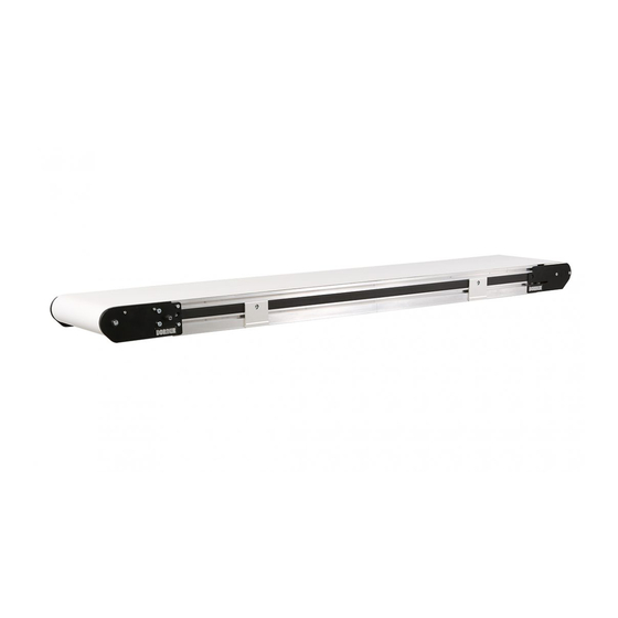
3 = Manual tracking 4 = V–guide tracking E = Elevating D = Declining * See Ordering and Specifications Catalog for details. Figure 2 Flat Belt Center Drive LPZ Conveyor Installation, Maintenance & Parts Manual Dorner Mfg. Corp. 851-518 Rev. A... - Page 4 32M080HHD9DEN 5.0–50.0 1.5–15.2 32M060HHD9DEN 6.7–66.7 2.0–20.3 (vp) = voltage and phase 11 = 115 V, 1-phase 23 = 208 – 230/460 V, 3-phase Flat Belt Center Drive LPZ Conveyor Installation, Maintenance & Parts Manual 851-518 Rev. A Dorner Mfg. Corp.
- Page 5 11 = 115 V, 1-phase 23 = 208 – 230/460 V, 3-phase NOTE: For belt speed other than those listed, con- tact factory for details. Flat Belt Center Drive LPZ Conveyor Installation, Maintenance & Parts Manual Dorner Mfg. Corp. 851-518 Rev. A...
-
Page 6: Installation
D Mount gearmotor mounting package (see page 9 for instructions) D Attach guides/accessories (see page 38 through 44 of Figure 5 “Service Parts” section for details) Flat Belt Center Drive LPZ Conveyor Installation, Maintenance & Parts Manual 851-518 Rev. A Dorner Mfg. Corp. -
Page 7: Mounting Brackets
Figure 11) to conveyor with mounting screws (AA). Figure 8 Slide belt (P of Figure 9) over assembled conveyor sections (Z). Figure 9 Flat Belt Center Drive LPZ Conveyor Installation, Maintenance & Parts Manual Dorner Mfg. Corp. 851-518 Rev. A... -
Page 8: Return Rollers
Remove screws (AG of Figure 12) and clips (AH) from roller assembly. Install roller assemblies (AI of Figure 13) as shown. Figure 15 Tighten screws (AG) to 60 in-lb (7 Nm). Flat Belt Center Drive LPZ Conveyor Installation, Maintenance & Parts Manual 851-518 Rev. A Dorner Mfg. Corp. -
Page 9: Gearmotor Installation
Cover Cover Bolts Motor Mount Bolts Spacer Ring NOTE: Gearmotor may be operated in positions 1, 3 or 4 (Figure 17). Figure 19 Flat Belt Center Drive LPZ Conveyor Installation, Maintenance & Parts Manual Dorner Mfg. Corp. 851-518 Rev. A... -
Page 10: Preventative Maintenance & Adjustment
D Stalling or slipping other harsh chemicals. D Damage to V-guide Use Dorner Belt Cleaner (part # 625619). Mild soap and Surface cuts and wear indicate: water may also be used. Do not soak the belt. D Sharp or heavy parts impacting belt... -
Page 11: Conveyor Belt Replacement
If equipped, remove return rollers and guiding and accessories from one side of conveyor. Temporarily support idler guard assembly (AX of Figure 23). Remove screws (AY). Figure 25 Flat Belt Center Drive LPZ Conveyor Installation, Maintenance & Parts Manual Dorner Mfg. Corp. 851-518 Rev. A... - Page 12 Figure 27 Push shaft (BF of Figure 27) through block, slide block (BG of Figure 28) towards air cylinder (BH). Figure 31 Figure 28 Flat Belt Center Drive LPZ Conveyor Installation, Maintenance & Parts Manual 851-518 Rev. A Dorner Mfg. Corp.
-
Page 13: Belt Removal For Conveyor With Stands
Start on one end of conveyor and Remove belt (BJ of Figure 34) from conveyor. work down to opposite end. Figure 34 Figure 36 Flat Belt Center Drive LPZ Conveyor Installation, Maintenance & Parts Manual Dorner Mfg. Corp. 851-518 Rev. A... -
Page 14: Belt Installation For Conveyor Without Stands
If equipped, install wipers, return rollers and guid- “Center Drive Module Tracking“ section on page 16 and “Conveyor Belt Tracking” section on page 15. ing. Flat Belt Center Drive LPZ Conveyor Installation, Maintenance & Parts Manual 851-518 Rev. A Dorner Mfg. Corp. -
Page 15: Conveyor Belt Tensioning
Preventive Maintenance and Adjustment Reattach air supply (AW of Figure 39) to center Suggested Tensioning Air Pressure for LPZ & drive. Refer to “Conveyor Belt Tensioning” section 3200 Series Flat Belt Center Drive Conveyors on page 15 for more information. Width Pressure 4”... - Page 16 Figure 45)with a 5 mm hex-key wrench to 146 in-lb Rotate the tracking cam (BZ of Figure 51) in small (16.5 Nm). increments, each time inspecting the belt as it exits Flat Belt Center Drive LPZ Conveyor Installation, Maintenance & Parts Manual 851-518 Rev. A Dorner Mfg. Corp.
-
Page 17: Conveyor Angle Adjustment
Place temporary support (CA of Figure 52) under Tighten screws (CB of Figure 53) on both sides of conveyor sections. knuckle to 100 in–lbs (12 N–m). Flat Belt Center Drive LPZ Conveyor Installation, Maintenance & Parts Manual Dorner Mfg. Corp. 851-518 Rev. A... -
Page 18: End And Knuckle Pulley Removal
(T of Figure 59) and remove two (2) front fastening screws (CD). Figure 56 Swing down idler guard assembly (AX of Figure 57). Figure 59 Flat Belt Center Drive LPZ Conveyor Installation, Maintenance & Parts Manual 851-518 Rev. A Dorner Mfg. Corp. -
Page 19: B - Transfer Tail Pulley Removal
(T of Figure 65), and remove the side of the pulley assembly. two (2) front fastening screws (CD). Figure 62 Figure 65 Flat Belt Center Drive LPZ Conveyor Installation, Maintenance & Parts Manual Dorner Mfg. Corp. 851-518 Rev. A... -
Page 20: C - Knuckle Idler Pulley Removal
Remove hex nuts (CK of Figure 68). Figure 71 On one side of knuckle, remove screws (CP of Figure 68 Figure 72) and knuckle plate assembly (CQ). Flat Belt Center Drive LPZ Conveyor Installation, Maintenance & Parts Manual 851-518 Rev. A Dorner Mfg. Corp. -
Page 21: D - Knuckle Return Roller Removal
(BN). Figure 74 Slide the shaft assembly (CI of Figure 63) out of the Figure 77 pulley (CR). Flat Belt Center Drive LPZ Conveyor Installation, Maintenance & Parts Manual Dorner Mfg. Corp. 851-518 Rev. A... -
Page 22: Center Drive Pulleys Removal
Remove screws (BA of Figure 79) and tensioning guards (BB) from both sides of center drive. 81) on one side of center drive. Flat Belt Center Drive LPZ Conveyor Installation, Maintenance & Parts Manual 851-518 Rev. A Dorner Mfg. Corp. - Page 23 (BH). Figure 83 Slide out tensioning pulley (BI of Figure 84). Figure 86 Flat Belt Center Drive LPZ Conveyor Installation, Maintenance & Parts Manual Dorner Mfg. Corp. 851-518 Rev. A...
- Page 24 Remove screws (CV of Figure 89) and idler guide Figure 91 side plate (CW). Slide the shaft assembly (CI of Figure 92) out of the pulley (CF). Figure 89 Flat Belt Center Drive LPZ Conveyor Installation, Maintenance & Parts Manual 851-518 Rev. A Dorner Mfg. Corp.
- Page 25 Remove screws (DA of Figure 94) and remove gearmotor (DB) (NOTE: Gearhead shown with motor removed for clarity, motor can remain at- Figure 96 tached to gearhead). Flat Belt Center Drive LPZ Conveyor Installation, Maintenance & Parts Manual Dorner Mfg. Corp. 851-518 Rev. A...
-
Page 26: Bearing Replacement
Figure 99 – Drive Bearing – Transfer Tail Bearing Remove screws (DH) and pull side plate assembly (DI) off conveyor. – Knuckle Idler Bearing Flat Belt Center Drive LPZ Conveyor Installation, Maintenance & Parts Manual 851-518 Rev. A Dorner Mfg. Corp. -
Page 27: A - Idler Bearing Replacement
Remove spacer ring (AS of Figure 104) and key (AO). Loosen clamp screw (DC) and remove bearing collar (DD). – Idler Bearing Replacement The bearings in a 3200 Series Idler Pulley can not be removed. Replace the entire pulley assembly when worn. – Drive Bearing Removal and Replacement Ç... - Page 28 – Transfer Tail Bearing Replacement Remove screws (CY of Figure 108) and cover (CZ). The bearings in a 3200 Series Transfer Tail Pulley Loosen clamp screw (DC of Figure 109) and remove can not be removed. Replace the entire pulley bearing collar (DD).
-
Page 29: Transfer Tail Pulley
Preventive Maintenance and Adjustment Drive Pulley – Knuckle Idler Bearing Replacement The bearings in a 3200 Series Knuckle Idler Pulley To replace the drive pulley, reverse the “Drive Pulley can not be removed. Replace the entire pulley Removal” procedure on page 25. -
Page 30: Service Parts
Service Parts NOTE: For replacement parts other than those shown in this section, contact an authorized Dorner Service Center or the factory. Center Drive Assembly Flat Belt Center Drive LPZ Conveyor Installation, Maintenance & Parts Manual 851-518 Rev. A Dorner Mfg. Corp. - Page 31 Socket Head Screw M5 x 12mm 300895–05599 301198–05209 920520M Socket Head Screw M5 x 20mm 300895–05799 301198–05409 920610M Socket Head Screw M6 x 10mm 300895–05999 301198–05609 Flat Belt Center Drive LPZ Conveyor Installation, Maintenance & Parts Manual Dorner Mfg. Corp. 851-518 Rev. A...
- Page 32 Motor, 1.0hp (0.75Kw), 115 Volts, 826–394 Integrated Controller Motor, 0.5hp (0.37Kw), 115 Volts, 826–395 Integrated Controller 820–329 Bushing Shaft Adapter, 56C to 140TC Flat Belt Center Drive LPZ Conveyor Installation, Maintenance & Parts Manual 851-518 Rev. A Dorner Mfg. Corp.
-
Page 33: Transfer Tail Assembly
Low Head Socket Screw M8 x 16mm 3217WW 1” Idler Tail Axle Shaft WW = Conveyor width reference: 04 – 48 in 02 increments 3219WW Roller Assy Support Bar Flat Belt Center Drive LPZ Conveyor Installation, Maintenance & Parts Manual Dorner Mfg. Corp. 851-518 Rev. A... -
Page 34: Idler End Tail Assembly
Hex Tension Tracking Shaft 3202WW Tail Articulation Bar WW = Conveyor width reference: 04 – 48 in 02 increments 3284WW 3” Idler Pulley Flat Belt Center Drive LPZ Conveyor Installation, Maintenance & Parts Manual 851-518 Rev. A Dorner Mfg. Corp. -
Page 35: Knuckle Assembly
920692M Socket Low Head Screw M6 x 12mm 3225WW Return Roller Cover WW = Conveyor width reference: 04 – 48 in 02 increments Flat Belt Center Drive LPZ Conveyor Installation, Maintenance & Parts Manual Dorner Mfg. Corp. 851-518 Rev. A... -
Page 36: Frame Assembly
00600 for each Knuckle Attachment WW = Conveyor width reference: 04 – 48 in 02 increments LLLLL = Frame Length (see Bed Plate & Frame Formulas) Flat Belt Center Drive LPZ Conveyor Installation, Maintenance & Parts Manual 851-518 Rev. A Dorner Mfg. Corp. - Page 37 6” 6” 4” 6” 6” 6” 6” 4” 4” 72” 4” 4” 6” 6” 6” 6” 6” 6” 6” 6” 6” 4” 4” Flat Belt Center Drive LPZ Conveyor Installation, Maintenance & Parts Manual Dorner Mfg. Corp. 851-518 Rev. A...
-
Page 38: Conveyor Configurations
= Section length in feet from model number LLLLL = Guiding Length in inches (see pages 39 thru 43 for length formulas per section) Flat Belt Center Drive LPZ Conveyor Installation, Maintenance & Parts Manual 851-518 Rev. A Dorner Mfg. Corp. -
Page 39: Walk Through Frame - Section L1
38TT00–LLLLL 0400 and up 38TT15 38TT16 LLLLL = (LLLL x 12) – 02400 For TT options see “Guide Options” section on page 38 Flat Belt Center Drive LPZ Conveyor Installation, Maintenance & Parts Manual Dorner Mfg. Corp. 851-518 Rev. A... -
Page 40: Walk Through Frame - Section L2
0601 and up 38TT15 38TT16 38TT17 38TT18 LLLLL = (LLLL x 12) – 04600 For TT options see “Guide Options” section on page 38 Flat Belt Center Drive LPZ Conveyor Installation, Maintenance & Parts Manual 851-518 Rev. A Dorner Mfg. Corp. -
Page 41: Walk Through Frame - Section L3
38TT00–LLLLL 0400 and up 38TT17 38TT18 LLLLL = (LLLL x 12) – 02400 For TT options see “Guide Options” section on page 38 Flat Belt Center Drive LPZ Conveyor Installation, Maintenance & Parts Manual Dorner Mfg. Corp. 851-518 Rev. A... -
Page 42: Noseover Frame - Section L2
38TT00–LLLLL 0400 and up 38TT15 38TT16 LLLLL = (LLLL x 12) – 02400 For TT options see “Guide Options” section on page 38 Flat Belt Center Drive LPZ Conveyor Installation, Maintenance & Parts Manual 851-518 Rev. A Dorner Mfg. Corp. -
Page 43: Noseover Frame - Section L3
38TT00–LLLLL 0400 and up 38TT17 38TT18 LLLLL = (LLLL x 12) – 02400 For TT options see “Guide Options” section on page 38 Flat Belt Center Drive LPZ Conveyor Installation, Maintenance & Parts Manual Dorner Mfg. Corp. 851-518 Rev. A... -
Page 44: -13 Adjustable Guiding
Socket Head Screw M6 x 12mm 202992 Aluminum Profile Guide 11’ (3353mm) 920616M Socket Head Screw M6 x 16mm 202993 Aluminum Profile Guide 12’ (3658mm) Flat Belt Center Drive LPZ Conveyor Installation, Maintenance & Parts Manual 851-518 Rev. A Dorner Mfg. Corp. -
Page 45: Flat Belt Mounting Bracket
Connecting Assembly without Stand Mount Item Part Number Description 240859 Intermediate Clamp Plate 240858 Frame Bar Connector 920692M Socket Head Screw M6 x 12mm Flat Belt Center Drive LPZ Conveyor Installation, Maintenance & Parts Manual Dorner Mfg. Corp. 851-518 Rev. A... -
Page 46: 4" (102Mm) To 6" (152Mm) Flat Belt Return Roller
Part Number Description 802–123 Bearing 240825 Short Return Roller Guard 913–100 Dowel Pin 240827 Return Roller Clip 920693M Socket Head Screw M6 x 16mm Flat Belt Center Drive LPZ Conveyor Installation, Maintenance & Parts Manual 851-518 Rev. A Dorner Mfg. Corp. -
Page 47: 8" (203Mm) To 48" (1219Mm) Flat Belt Return Roller
Socket Head Screw M6 x 16mm 240827 Return Roller Clip WW = Conveyor width reference: 08 – 48 in 02 increments 2409WW Return Roller Guard Flat Belt Center Drive LPZ Conveyor Installation, Maintenance & Parts Manual Dorner Mfg. Corp. 851-518 Rev. A... -
Page 48: Conveyor Belt Part Number Configuration
HARTLAND, Figure 112 Flat Belt Part Number Configuration Refer to Dorner patent plate (Figure 112). From the model number, determine conveyor tracking (”T”), drive/tail type (”D”), width (“WW”), length (“LLLL”) and belt type (“BB”). Use data to configure belt part number as indicated below. - Page 49 Notes Flat Belt Center Drive LPZ Conveyor Installation, Maintenance & Parts Manual Dorner Mfg. Corp. 851-518 Rev. A...
-
Page 50: Return Policy
Authorization Number to reference. There will be a 15% restocking charge on all new items returned for credit where Dorner was not at fault. These will not be accepted after 60 days from original invoice date. The restocking charge covers inspection, cleaning, disassembly, and reissuing to inventory.
Need help?
Do you have a question about the 3200 Series and is the answer not in the manual?
Questions and answers