Table of Contents
Advertisement
Quick Links
DIAPHRAGM PUMP SET
DPS 90 F
DPS 90 F
DPS 90 FN
DPS 90 FN
This ANEST-IWATA diaphragm paint pump complies to ATEX regulations 94/9/EC.
Protection level: II 2 GX Suitable for use in Zones 1 and 2.
X marking:
Any static electricity discharge from the pump is to be diverted to the ground through the
grounding wire which is included in this product.
Instruction Use and Maintenance Manual
Series
Series
Series
Series
GB
Advertisement
Table of Contents

Subscribe to Our Youtube Channel
Related Manuals for Anest Iwata DPS 90 F Series


Summary of Contents for Anest Iwata DPS 90 F Series
- Page 1 Instruction Use and Maintenance Manual DIAPHRAGM PUMP SET DPS 90 F Series DPS 90 F Series DPS 90 FN Series DPS 90 FN Series This ANEST-IWATA diaphragm paint pump complies to ATEX regulations 94/9/EC. Protection level: II 2 GX Suitable for use in Zones 1 and 2. X marking: Any static electricity discharge from the pump is to be diverted to the ground through the grounding wire which is included in this product.
- Page 2 ANEST IWATA EUROPE TORINO - ITALY The company ANEST IWATA EUROPE Srl mission is to supply all their product and spray painting equipment users and distributors with the STATE-OF-THE-ART of technology and with continuous innovations, to obtain the best finish at the lowest cost.
-
Page 3: Table Of Contents
CONTENTS CONTENTS ………………………………………………………………………………………………PAGE USE OF THE MANUAL ………………………………………………………………………………………4 SYMBOLS USED ……………………………………………………………………………………………4 INFORMATIVE LETTER………………………………………………………………………………………5 WARRANTY ……………………………………………………………………………………………………7 IMPORTANT INFORMATION-SAFETY PRECAUTION …………………………………………………8 SAFETY WARNING …………………………………………………………………………………………9 TRANSPORT AND HANDLING ……………………………………………………………………………11 TRANSPORT …………………………………………………………………………………………………11 TRANSPORT WITH CARDBOARD PACKAGING ………………………………………………………11 HANDLING ……………………………………………………………………………………………………12 TEMPORARY STORAGE …………………………………………………………………………………12 PRODUCT IDENTIFICATION ………………………………………………………………………………13 PLATE DATA …………………………………………………………………………………………………13 MODELS ……………………………………………………………………………………………………14... -
Page 4: Use Of The Manual
Use of The use and maintenance manual is the document accompanying the equipment from its manufactu- the manual re till its dismantling. Therefore, it is an integral part of the equipment. The manual must be read before starting ANY ACTIVITY involving the equipment including its hand- ling. -
Page 5: Informative Letter
Informative This use and maintenance manual is an integral part of the equipment and it must be easily Letter available to the staff in charge of its use and maintenance. The user and the maintenance man must know the content of this manual. All the descriptions and pictures contained in this manual are not binding. - Page 6 WARNING In case of breakdown or malfunction, apply to the Customer Car Service. CUSTOMER SERVICE ANEST IWATA EUROPE s.r.l. C.so Vigevano, 46 - 10155 Torino Telephone +39 011.24.80.868 Telefax +39 011.85.19.44 E-mail: info@anest-iwataeu.com WARNING THE ORIGINAL CONFIGURATION OF THE EQUIPMENT MUST NOT BE CHANGED AT ALL.
-
Page 7: Warranty
Warranty All ANEST IWATA S.r.l. products have a one-year guarantee from the invoice date, unless otherwise stated in writing. The warranty covers all manufacturing faults and material defects. Any spare part replacement or repair operations are covered only if they are carried out by our technicians at our servicing shops. -
Page 8: Important Information-Safety Precaution
Important information - Safety precaution • Be sure to read and understand this instruction manual. The operator shall be fully conversant with the requirements stated within this instruction manual including important warnings, cau- tions and operations. • Wrong operation (mishandling) can cause serious bodily injury, death, fire or explosion. SAFETY FACTOR •... -
Page 9: Safety Warning
1. SAFETY WARNING WEAR PROTECTIVE GEAR During painting, be sure to wear protective gear such as glasses, mask or gloves to avoid serious injury caused by paints or solvents which might enter your eyes or you might inhale. BE CAREFUL ABOUT VENTILATION Use it in a well-ventilated area. - Page 10 WARNING! BE CAREFUL ABOUT EXPLOSION Be sure to use paint pump at less than max. air inlet pressure (check section 3. specifications). Use at more than max. air operating pressure can cause explosion of pump resulting in great dan- ger. Be sure to use paint pump at less than max.
-
Page 11: Transport And Handling
2. TRANSPORT AND HANDLING TRANSPORT To transport the equipment only the systems described below can be used. In any case make sure that the transport and lifting device can bear the weight of the equipment with its packaging. WARNING ALWAYS KEEP THE PACKAGING IN VERTICAL POSITION. WARNING IT IS ADVISABLE THAT THE STAFF IN CHARGE OF HANDLING THE EQUIPMENT WEAR PROTEC- TIVE GLOVES AND SAFETY SHOES. -
Page 12: Handling
HANDLING To handle the cardboard packaging use a trolley. WARNING FOLLOW THE INSTRUCTIONS ON THE PACKAGING BEFORE HANDLING AND OPENING IT. HANDLING BY MEANS OF HANDLE HANDLING BY MEANS OF TROLLEY TEMPORARY STORAGE During transport and storage make sure the temperatures between 0 and 40° C are not exceeded. In case of storage, make sure the equipment is not put in places with an excessive humidity. -
Page 13: Product Identification
3. PRODUCT IDENTIFICATION PLATE DATA The manufacturer’s identification plate is applied on the diaphragm pump (see picture below). It must not be removed at all, even if the equipment is resold. For any communication with the manu- facturer always mention the serial number written on the plate itself. Model Serial number Max air working pressure... -
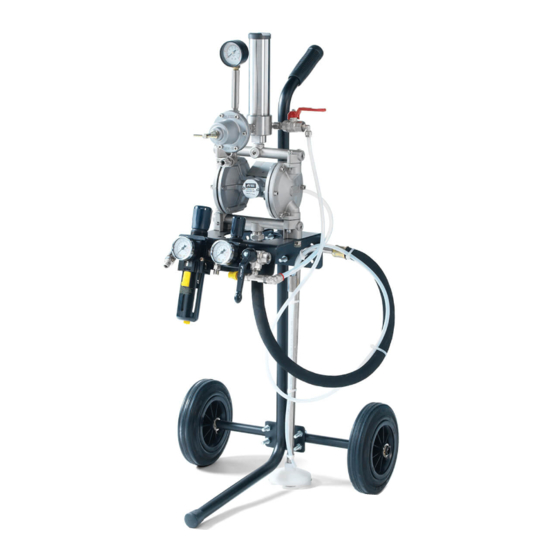
Page 14: Models
MODELS The following pump models are available: SOLVENT-BASED PAINT MODELS Base Model: Pump casing type DDP 90F SIPHON MODELS: DPS 901 F: Pump type DDP 90 F mounted on a stand with PR-5L paint pressure regulator, 2 air pressure redu- cers (for pump and gun), dip tube with filter, paint filter unit, fluid recirculation, 2 safety devices (1 overpressure valve, 1 ball valve ). -
Page 15: Thecnical Specifications
TECHNICAL SPECIFICATIONS MODEL DIMENSIONS [mm] WEIGHT [Kg] DPS 901 F 500x430x1015 11.9 DPS 901 FG 500x430x1015 11.05 DPS 902 F 360x335x760 11.12 DPS 903 F 500x500x1055 15.9 DPS 904 F 360x260x600 11.4 DPS 9036 F 535x500x1055 16.6 DPS 901 FN 500x430x1015 11.9 DPS 903 FN... - Page 16 DPS 902-F DPS 901F DPS 901 FG (without PR5L) DPS 901 FN DPS 903-F DPS 903-FN...
- Page 17 DPS 904-F DPS 904-FN DPS 9036-F DPS 9036-FN...
-
Page 18: Safety Systems
SAFETY SYSTEMS Several safety systems have been conceived during the diaphragm pump design and manufacture to safeguard the operator, in compliance with pr EN 12621 Directive about paint. SAFETY INFORMATION In case of units that are to be used in areas with potentially explosive atmospheres, before starting working the operators must disable the unit power supply, by putting it “out of order”. -
Page 19: Safety Indications
The Company ANEST IWATA is not to be held responsible for any accident due to the pump use by an UNAUTHORIZED and non qualified staff using it for purposes that are different from the above mentioned ones. -
Page 20: Pump Operation
4. PUMP OPERATION OPERATION DESCRIPTION Based on a simple manufacture, the operation consists in two diaphragm movement, which are both fixed at the end of a rod, pressurizing and sending the paint. The compressed air enters the air chamber from side A in picture 1. The diaphragm is moved to the left, by pushing the paint. -
Page 21: Installation And Starting
5. INSTALLATION AND STARTING CHECK ON THE PURCHASED PRODUCT Before using the pump, make sure it has not been damaged during transport or storage. Also check that all standard components are inside the packaging. CONDITIONS FOR INSTALLATION The installer must know the ATEX classification of the installation area, as well as the risks coming from a potentially explosive atmosphere, by paying attention to the explosion and fire risks so as to adopt the most suitable protections. -
Page 22: Installations Of Models
INSTALLATION OF MODELS: 1. Support the pump and unscrew the two 2. Place the pump in the right direction and M8x12 screws by means of a 6 mm Allen screw again the M8x12 screws. wrench. (For DPS 901 F/FN; 903 F/FN; (For DPS 901 F/FN;... - Page 23 5. Connect the suction pipe to the suction con- 6. Connect the recirculation pipe to the nector (1-47 on page 44). two-way valve for paint recirculation. (For DPS 901 F/FN; 903 F/FN; 904 F/FN; (For DPS 901 F/FN; 903 F/FN; 9036 F/FN) 904 F/FN;...
- Page 24 9. Connect the recirculation pipe to the two way valve for paint recirculation. (For DPS - 9036F/FN) 10. For the models with wall mounting bracket the pump is already in the right position. After fastening the pump, just connect the suction pipe. (For DPS - 904F/FN) 11.
- Page 25 14. Connect the air supply coming from the 15. Fasten the pump to the ground by means compressor to the inlet connector. of the bracket welded on the trailer or on (For all DPS - 90 F/FN series) the stand. (For DPS - 903 F/FN; 901 F/FN) Connect ground wire set to ground.
-
Page 26: Use
It is not to be held responsible for any carelessness during the pump use, either. If the system is used improperly, it could be broken by causing serious damage. Do not change the system; use only Anest Iwata original spare parts. Check the system daily: repair or replace immediately all worn or damaged parts. -
Page 27: Prewash
PREWASH 1. Make sure the pump is installed correctly (see section 5.3). 2. Soak the dip tube into the washing liquid, or fill the hopper or the tank according to the model used. 3. Put the ball valve in the right position. 4. - Page 28 Adjust the PR-5L paint pressure regulator as required (from 0 to 3.0 bar). Adjust the spraying air by means of the reducer (Pos. F on page 29) and test the gun on a panel before using it. PRECAUTIONS a) Use the gun under pressure. b) When the paint level inside the tank decreases, the pump can suck some air.
-
Page 29: Daily Interruptions
DAILY INTERRUPTIONS When the pump is stopped: - The air supply must not be disconnected if the interruption is short. - If the interruption is long, turn the Ball valve discharge the air from the cir- cuit and open the recirculation valve , to release the residual fluid pressure. -
Page 30: Wrong And Dangerous Uses
WRONG AND DANGEROUS USES A wrong earthing, an insufficient ventilation, a naked flame or a spark can cause a fire or an explosion and provoke some serious injuries. WARNING IF SOME SPARKS OR AN ELECTRIC DISCHARGE WERE PERCEIVED, INTERRUPT IMMEDIA- TELY ALL PAINTING OPERATIONS. -
Page 31: Pressure Release Process
PRESSURE RELEASE PROCESS WARNING 1. Close the air to the gun. 2. Close the air to the pump (BallValve ). 3. Make sure the recirculation pipe is not clogged. Then open gradually the recirculation two-way valve and leave it open. 4. -
Page 32: Maintenance And Inspections
7. MAINTENANCE AND INSPECTION GENERAL NOTES • Comply with the inspection and ordinary maintenance intervals so as to ensure suitable working conditions and explosion-proof protection. • Before carrying out any maintenance operation or repair on the internal parts, discharge completely air and fluid pressure inside the pump set. -
Page 33: Diaphragm Pump Disassembly From It Base Support
Some paint residues could remain inside the regulator: discharge them into the paint tank by overturning the pressure regulator itself. Paint filter Pump casing (1-43) Lid (1-24) Upper adaptor (1-45) Rod (1-36) Diaphragm (1-31/1-32) “UP” trade-mark “ANEST IWATA” trade-mark Lower adaptor (1-46) -
Page 34: Lid And Connector Disassembly
LID AND CONNECTOR DISASSEMBLY Packing Bolt Use a 5mm Hex. Bar spanner. 1. Loosen the four bolts and remove Upper adaptor upper adaptor. 2. Loosen the four bolts and remove lower adaptor. 3. Remove the four packings. Bolt 4. Loosen the six bolts and remove lid each side. - Page 35 Diaphragm holder (inside) 2. Remove the following parts from rod: Diaphragm (Black) - Nut - Spring washer Diaphragm (White) - Diaphragm holder (outside) - O’ring - Diaphragm set (White:outside- Black:inside) Spring washer - Diaphragm holder (inside) O’ring Diaphragm holder (outside) 3.
-
Page 36: Rod Disassembly
ROD DISASSEMBLY IMPORTANT Do not damage or bend rod and be sure to check the rod is free of foreign matter. It can cause pump malfunction. Do not damage or scratch the guide inside the main body. It can cause pump malfunction. Be sure to set Y shaped packing and o-ring correct way. -
Page 37: Pr-5L , Pr-5L N Paint Regulator Maintenance, Disassembly & Assembly
7.10 PR-5L - PR-5L N PAINT REGULATOR MAINTENANCE, DISASSEMBLY AND ASSEMBLY MODEL PR-5L Weight 850 g Max. flow 2.0 l/min Max. primary pressure 25.0 bar Pressure range 3.0 bar Connection IN G 3/8” Connection OUT G 1/4” PR-5L : aluminium body (for DPS series) PR-5LN : stainless steel body (for DPS FN series) - Page 38 IMPORTANT When you disassemble main body, rising pipe and pressure gauge, apply sealing agent to each threaded section to keep airtightness. Whenever disassembling ball and seat of tungsten carbide, you have be sure to confirm that there is no wear or damage. If there is any wear or damage, replace with new one. DISASSEMBLING Fully loosen handle set (22), and remove bolt with hex.
- Page 39 ASSEMBLING Check on each section if there are damage and foreign matter . Fit diaphragm holder (11), diaphragm (12), O ring (14), diaphragm holder (13) and spring washer (15) into diaphragm bolt (10) and tighten hex. nut (16).Tightening torque of hex. nut 9.8N-m Mount diaphragm section, adjusting spring (18), spring stopper (20), and diaphragm cap (19) on main body (8), and evenly tighten bolts with hex.
-
Page 40: Paint Filter Maintenance
IMPORTANT Fit tungsten carbide seat to main body so that tungsten carbide ball can be fitted on tapered side. Do not forget to fit packing. Wrong assembling can cause wrong movement of pointer of pressure gauge due to leakage from seat, failing performance. Pay attention to tightening torque when fitting joint (1). -
Page 41: Troubleshooting
8. TROUBLESHOOTING IMPORTANT Spare parts marked by [#] must be ANEST IWATA original items. If not, it can cause failure. PROBLEMS CAUSES REMEDIES a) The compressed air does not reach the a) Connect the compressed air. pump air inlet b) The air pressure is too low to start the pump b) Supply a sufficient air pressure restart (minimum 2.0 bar) - Page 42 PROBLEMS CAUSES REMEDIES The following parts are unscrewed or damaged a) The pump suction connector (1-47) a) Check if some tightening are loosened with the suction pipe and tighten them. b) The suction connector (1-47) b) Put some adhesive and tighten. c) The lower adaptor (1-46) c) Tighten.
- Page 43 PROBLEMS CAUSES REMEDIES The paint regulator is closed? Open the paint regulator Check air sources. a) Restore the air pipe a) The air flow is interrupted by the air pipe bending a) Restore the air pipe b) The air pressure is too low to start the pump b) Supply a sufficient air pressure (minimum 2,0 bar).
-
Page 44: Part List
9. SPARE PART LIST DIAPHRAGM PUMP Ref. Description Cylinder Filter screw Filter # Filter bolt nut Handle(DPS-902F;903F;904F;9036F) 1 Packing # Packing # Nipple 1-10 Two way valve 1-11 Hose elbow joint 1-12 Spring pin 1-13 Body 1-14 Filter plug (DPS 901F/DPS 901FG) 1-14a Filter plug(DPS-902F;903F;904F;9036F) 1 1-14b... -
Page 45: Pr-5L , Pr-5L N Paint Regulator
9.2 PR-5L , PR-5L N PAINT REGULATOR Ref. Description PR5L FOR MODELS : Joint G3/8” M - DPS 901 F Valve spring - DPS 902 F Carbide ball O-ring - DPS 903 F Carbide seat - DPS 904 F Packing - DPS 9036 F Hex. -
Page 46: Air Regulator Set
9.3 AIR REGULATOR FOR DPS-901F/ 901FN Ref. Description Joint Rc. 1/4”-G1/4” 3-10 Air regulator 1/4” “T” joint 1/4” MFM Ball Valve with Exhaust Hole G1/4” FF Safety valve G1/4”-8 Bar Quick joint 90° 1/4” MF 3-10 Joint B.P. 1/4” M 90° 3-14 Pressure gauge (optional) 3-14 Optional... -
Page 47: Suction Hose Set
9.4 SUCTION HOSE SET PIC. 1 Ref. Description Pic.1 Suction hose set (DPS 901F/903F/904F) Pic.2 Suction hose set (DPS 902F) Pic.3 PIC. 2 Cover 50 mesh filter 100 mesh filter (OPTIONAL) PIC. 3 Spring Complete filter set NOTE: Stainless steel suction hose set used for DPS 90 FN series 9.5 ACCESSORIES LOW PRESSURE AIR AND PAINT TWIN HOSE Air and paint twin hose m 2.0 with nipples air 1/4”-1/4”... -
Page 48: Dismalting
All sheaths, flexible ducts and plastic or non metal components will have to be disposed of separa- tely. ANEST IWATA Europe S.r.l. 46, Corso Vigevano 10155, Torino Italy Direct Tel. +39 011 - 24 80 868 Fax +39 011 - 22 74 406 info@anest-iwataeu.com...
Need help?
Do you have a question about the DPS 90 F Series and is the answer not in the manual?
Questions and answers