Table of Contents
Advertisement
Instruction Use and Maintenance Manual
DIAPHRAGM PUMP SET
DDP 120 B Series
DDP 120 B.TE (Aluminium)
DDP 120 BN.TE (Stainless Steel)
DDP 120 B WB.TE (Anodized Aluminium)
DPS 120 C Series
DPS 120 C.TE (Aluminium)
DPS 120 CN.TE (Stainless Steel)
DPS 120 C WB.TE (Anodized Aluminium)
DDP 90 E Series
DDP 90 E.TE (Aluminium)
DDP 90 EN.TE (Stainless Steel)
DDP 90 E WB.TE (Anodized Aluminium)
DPS 90 G Series
DPS 90 G.TE (Aluminium)
DPS 90 GN.TE (Stainless Steel)
DPS 90 G WB.TE (Anodized Aluminium)
This ANEST-IWATA diaphragm paint pump complies to ATEX regulations 94/9/EC.
Protection level: II 2 GX Suitable for use in Zones 1 and 2.
X marking:
Any static electricity discharge from the pump is to be diverted to the ground through
the grounding wire which is included in this product.
GB
Advertisement
Table of Contents

Related Manuals for Anest Iwata DDP 120 B Series


Summary of Contents for Anest Iwata DDP 120 B Series
- Page 1 Instruction Use and Maintenance Manual DIAPHRAGM PUMP SET DDP 120 B Series DDP 120 B.TE (Aluminium) DDP 120 BN.TE (Stainless Steel) DDP 120 B WB.TE (Anodized Aluminium) DPS 120 C Series DPS 120 C.TE (Aluminium) DPS 120 CN.TE (Stainless Steel) DPS 120 C WB.TE (Anodized Aluminium)
-
Page 2: Table Of Contents
CONTENTS USE OF THE MANUAL ………………………………………………………………………………………3 WARRANTY ……………………………………………………………………………………………………3 SAFETY WARNING …………………………………………………………………………………………4 TRANSPORT AND HANDLING ……………………………………………………………………………6 TRANSPORT …………………………………………………………………………………………………6 TRANSPORT WITH CARDBOARD PACKAGING ………………………………………………………6 HANDLING ……………………………………………………………………………………………………6 TEMPORARY STORAGE ……………………………………………………………………………………7 CHECK ON THE PURCHASED PRODUCT ………………………………………………………………7 PRODUCT IDENTIFICATION ………………………………………………………………………………8 PLATE DATA …………………………………………………………………………………………………8 THECNICAL SPECIFICATIONS ……………………………………………………………………………9 DPS MODELS DIMENSIONS &... -
Page 3: Use Of The Manual
MANUFACTURING COMPANY. Warranty All the products of ANEST IWATA Srl have a one-year warranty from invoice date, unless otherwise stated in writing. The warranty covers all manufacturing faults and material defects. Any spare part replacement or repair operation is covered only if it is carried out by our technicians at our servicing shops. -
Page 4: Safety Warning
1. SAFETY WARNING • Be sure to read and understand this instruction manual. The operator shall be fully conversant with the requirements stated within this instruction manual including important warnings, cau- tions and operations. • Wrong operation (mishandling) can cause serious bodily injury, death, fire or explosion. SAFETY FACTOR •... - Page 5 CONNECT GROUNDING Securely ground pump, spray gun, workpieces and containers containing paint or solvent. Be sure to use ground wire set supplied with pump set. Connect it to ground to have continuous grounding. Insufficient grounding will cause explosion or fire if exposed to a spark of electricity. WARNING! BE CAREFUL ABOUT EXPLOSION Be sure to use paint pump at less than max.
-
Page 6: Transport And Handling
2. TRANSPORT AND HANDLING TRANSPORT To transport the equipment only the systems described below can be used. In any case make sure that the transport and lifting device can bear the weight of the equipment with its packaging. WARNING ALWAYS KEEP THE PACKAGING IN VERTICAL POSITION. WARNING IT IS ADVISABLE THAT THE STAFF IN CHARGE OF HANDLING THE EQUIPMENT WEAR PROTECTIVE GLOVES AND SAFETY SHOES. -
Page 7: Temporary Storage
TEMPORARY STORAGE During transport and storage make sure the temperatures between 0 and 40° C are not exceeded. In case of storage, make sure the equipment is not put in places with an excessive humidity. CHECK ON THE PURCHASED PRODUCT When you receive and before using the pump, make sure it has not been damaged during transport or storage. -
Page 8: Product Identification
3. PRODUCT IDENTIFICATION PLATE DATA The manufacturer’s identification plate is applied on the diaphragm pump (see picture below). It must not be removed at all, even if the equipment is resold. For any communication with the manu- facturer always mention the serial number written on the plate itself. Model Serial number Max air working pressure... -
Page 9: Thecnical Specifications
4. TECHNICAL SPECIFICATIONS Pump Version DPS-120C.TE DPS-90G.TE PUMP Type DDP-120B DDP-120BN DDP-120B-WB DDP-90E DDP-90EN DDP-90E-WB Stainless Stainless Anodized Anodized Paint Passages Aluminum Aluminum Aluminum Aluminum Steel Steel Air Working 1.5~7 bar Pressure Range 22~100 psi Max. Fluid 7 bar (100 psi) Working Pressure Air Inlet G 1/4”... -
Page 10: Dps_Models
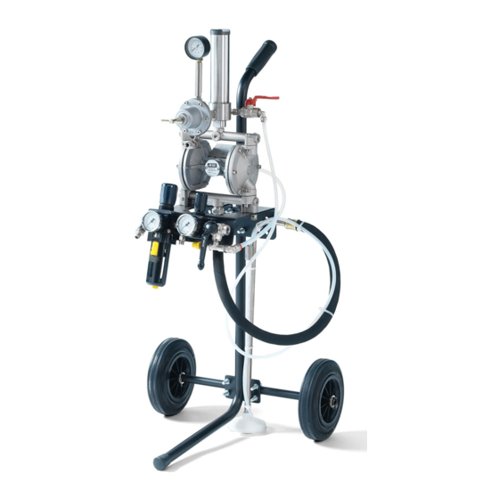
DPS_MODELS STAND TYPE DPS 120-1C.TE/CN.TE/C-WB.TE DDP version mounted on stand, with paint regulator, 2 air regulators (for pump and DPS 90-1G.TE/GN.TE/G-WB.TE gun), paint filter unit, dip tube with filter, fluid recirculation, 1 overpressure valve, ball valve with exhaust hole. • PR-5BL paint regulator for DPS 120-1C.TE and DPS 90-1G.TE •... - Page 11 WALL MOUNT TYPE DPS 120-4C.TE/CN.TE/C-WB.TE DDP version mounted on wall mounting bracket with paint regulator, 2 air regulators DPS 90-4G.TE/GN.TE/G-WB.TE (for pump and gun), paint filter unit, dip tube with filter, fluid recirculation, 1 overpres- sure valve, ball valve with exhaust hole. •...
-
Page 12: Safety Systems
SAFETY SYSTEMS Several safety systems have been conceived during the diaphragm pump design and manufacture to safeguard the operator, in compliance with pr EN 12621 Directive about paint. SAFETY VALVE A 7 bar calibrated safety valve is installed to ensure the pump working pressure does not exceed the limits inside the feeding circuit. -
Page 13: Workable Products
The Company ANEST IWATA is not to be held responsible for any accident due to the pump use by an UNAUTHORIZED and non qualified staff using it for purposes that are different from the above mentioned ones. -
Page 14: Pump Operation
5. PUMP OPERATION OPERATION DESCRIPTION Based on a simple manufacture, the operation consists in two diaphragm movement, which are both fixed at the end of a rod, pressurizing and sending the paint. The compressed air enters the air chamber from side A in picture 1. The diaphragm is moved to the left, by pushing the paint. -
Page 15: Installation And Starting
6. INSTALLATION AND STARTING CONDITIONS FOR INSTALLATION The installer must know the ATEX classification of the installation area, as well as the risks coming from a potentially explosive atmosphere, by paying attention to the explosion and fire risks so as to adopt the most suitable protections. -
Page 16: Installations Of Dps Models
INSTALLATION OF DPS_MODELS A - STAND TYPE / CART TYPE COMMON 1. Remove the dust proof caps (B,E,F,H,I on page 21) 1. Connect the drain hose 2. Detach the pump assembly from the support by removing Hex. Bolts (M8) to the two-way valve for 3. - Page 17 C - CART TYPE 1. Assemble the following parts below in numerical order, and fix them to the stand. 3. Tire 4. Washer Hex. Nut 2. Washer Axle U bolt 1. Snap pin* 5. Snap pin* * Put the end of the pin into axle hole, and push it inside all the way by using hammer As is when is fitted 2.
- Page 18 D - WALL MOUNTING TYPE 1. Remove the dust proof caps (B,E,F,H,I on page 21) 2. Detach the pump assembly from bracket by removing hex. Bolts (M8) 3. Flip the bracket and assemble the pump to the right position on bracket by using hex. Bolts (M8). 4.
-
Page 19: Use
It is not to be held responsible for any carelessness during the pump use, either. If the system is used improperly, it could be broken by causing serious damage. Do not change the system; use only Anest Iwata original spare parts. Check the system daily: repair or replace immediately all worn or damaged parts. -
Page 20: Starting
WARNING THE PUMP MUST BE WASHED BEFORE USING IT FOR THE FIRST TIME, IF IT IS NOT USED FOR A LONG TIME AND AFTER ANY COLOUR CHANGE. STARTING Before beginning working, start the pump by following the instructions below: 1. Connect ground wire set to ground. 2. -
Page 21: Wrong And Dangerous Uses
A) Exhaust Ball valve B) Two-way valve for paint recirculation C) Pump air pressure reducer D) Gun air pressure reducer E) Feeder line connection F) Air connection to gun G) Safety valve H) Paint inlet joint I) Paint pressure regulator Dust proof cap (female) : B) , E) , F) , H) , I) Tank mount model : H) is not included (Dust proof cap male) WRONG AND DANGEROUS USES... -
Page 22: Pressure Release Process
PRESSURE RELEASE PROCESS WARNING 1. Close the air to the gun. 2. Close the air to the pump (exhaust ball valve). 3. Make sure the recirculation pipe is not clogged. Then open gradually the recirculation two-way valve and leave it open. 4. -
Page 23: Maintenance And Inspections
8. MAINTENANCE AND INSPECTION GENERAL NOTES A suitable maintenance is important for a longer duration of the equipment in good working condi- tions and efficiency ensuring functional safety as time goes by. All maintenance operations must be carried out by a qualified staff. The pump design and the mate- rials used to manufacture it limit the maintenance interventions to a simple periodic cleaning. -
Page 24: Lid, Connector &Air Operating Valve Disassembly
8.5 LID AND CONNECTOR AND AIR OPERATING VALVE DISASSEMBLY Main body Upper Adaptor O’rings Diaphragm Lower Adaptor Bolt with hex. hole (M5) 8.6 DIAPHRAGM SET DISASSEMBLY A. Remove the two nuts with a 13mm spanner. D. Hold flat face of center of the rod with a 12mm spanner, and loosen the nut with a 13mm span- ner on the side where the diaphragm has not been removed yet and disassemble as described... -
Page 25: Intake And Exhaust Valve Disassembly
PRECAUTIONS Pay attention to the assembly direction of the “Y” packings (see the picture). Place the “Y” packings to the direction that they open outward. Lubricate the “Y” packing, the O’ring and the slots with some lithium grease. Tightening pressure of nuts : 8.83 Nm INTAKE AND EXHAUST VALVE DISASSEMBLY Press down the ball with a screwdriver by using stopper of the lid to remove... -
Page 26: Paint Regulator Maintenance, Disassembly & Assembly
8.10 PR-5BL - PR-5BL WB - PR-5BL N PAINT REGULATOR MAINTENANCE, DISASSEMBLY AND ASSEMBLY IMPORTANT When you disassemble main body, rising pipe and pressure gauge, apply sealing agent to each threaded section to keep airtightness. Whenever disassembling ball and seat of tungsten carbide, you have be sure to confirm that there is no wear or damage. -
Page 27: Paint Regulator Spare Parts
8.11 PR-5BL, PR-5BL WB, PR-5BLN PAINT REGULATOR SPARE PARTS Weight PR-5BL /-5 BL WB PR-5BLN Ref. Description 850 g 1020 g Joint G3/8” Max. flow 1.5 l/min Valve spring Max. primary pressure 7.0 bar Carbide ball Pressure range 3.0 bar O’ring Connection IN G 3/8”... -
Page 28: Troubleshooting
9. TROUBLESHOOTING IMPORTANT Spare parts marked by [#] must be ANEST IWATA original items. If not, it can cause failure. PROBLEMS CAUSES REMEDIES a) The compressed air does not reach the a) Connect the compressed air. pump air inlet b) The air pressure is too low to start the pump b) Supply a sufficient air pressure restart (minimum 2.0 bar) - Page 29 PROBLEMS CAUSES REMEDIES The following parts are unscrewed or damaged a) The pump suction connector a) Check if some tightening are loosened with the suction pipe and tighten them. b) The suction connector b) Put some adhesive and tighten. c) The lower adaptor c) Tighten.
- Page 30 PROBLEMS CAUSES REMEDIES The paint regulator is closed? Open the paint regulator Check air sources. a) The air flow is interrupted by the air pipe bending a) Restore the air pipe b) The air pressure is too low to start the pump b) Supply a sufficient air pressure (minimum 2,0 bar).
-
Page 31: Spare Parts List
10. SPARE PARTS LIST 10.1 DPS_DIAPHRAGM PUMP SET ASSEMBLY Ref. Item Paint regulator set Air regulator set Paint filter set Swivel joint Hex. socket bolt with washer Connecting bolt Nipple Ball valve Joint * Pipe Washer bolt for Stainless Steel &... -
Page 32: Ddp Diaphragm Spare Parts List
10.2 DDP_DIAPHRAGM PUMP SPARE PARTS LIST... -
Page 33: Air Operating Valve Spare Parts List
DDP_DIAPHRAGM PUMP SPARES PART LIST Parts subjects to wear: # Rif. Descrizione DDP 90 F DDP 120 B • Marked parts differt amoung Main body • Aluminium, Stainless Steel, • Anodized Aluminium. Upper Adaptor • Hexagon socket plug Lower Adaptor •... -
Page 34: Paint Filter Set
10.4 PAINT FILTER SET Ref. Description Body Filter Bolt Cylinder Cylinder cap Packing Packing Nipple Bolt cap Spring pin 10 Filter (100 mesh) 10.5 AIR REGULATOR SET Ref. Description Plate Air regulator set Pressure gauge R1/8” Elbow R1/4”x G1/4” Elbow R1/4”x R1/4” Ball valve Rc1/4”x R1/4”... -
Page 35: Suction Hose, Suction Pipe & Drain Hose
10.7 SUCTION HOSE, DIP TUBE WITH FILTER & DRAIN HOSE Ref. Description Pic. 1 SUCTION HOSE SET For STAND type - CART type - WALL BRACKET type Ref. Description Pic. 2 SUCTION PIPE SET For TANK type Ref. Description Pic. 3 FILTER COVER SET For All types Cover... -
Page 36: Dismalting
All sheaths, fl exible ducts and plastic or non metal components will have to be disposed of separa- tely. EUROPEAN SALES BRANCHES ANEST IWATA Europe S.r.l. ANEST IWATA Italia S.r.l. Corso Vigevano, 46 - 10155, Torino (IT) Tel. diretto +39 011 - 24 80 868 - Fax: +39 011 - 85 19 44 Direct Tel.
Need help?
Do you have a question about the DDP 120 B Series and is the answer not in the manual?
Questions and answers