Sign In
Upload
Manuals
Brands
Allied Telesis Manuals
Media Converter
MMC2000 Series
User Manuals: Allied Telesis MMC2000 Series Converter
Manuals and User Guides for Allied Telesis MMC2000 Series Converter. We have
1
Allied Telesis MMC2000 Series Converter manual available for free PDF download: Installation Manual
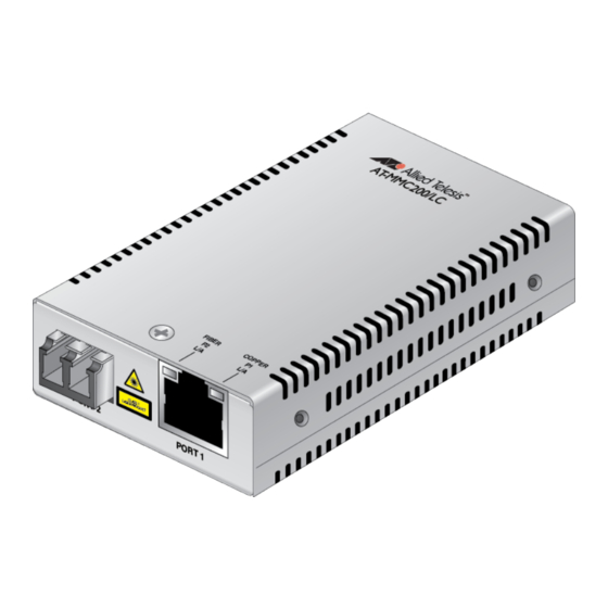
Allied Telesis MMC2000 Series Installation Manual (66 pages)
Mini Switching Media Converters
Brand:
Allied Telesis
| Category:
Media Converter
| Size: 9 MB
Table of Contents
Table of Contents
5
Preface
11
Symbol Conventions
12
Contacting Allied Telesis
13
Chapter 1 : Overview
15
Introduction
16
Front Panels
16
Figure 1: Front Panel for the MMC2000/200 Series Media Converters with the SC Connector
16
Figure 2: Front Panel for the MMC2000/200 Series Media Converters with the ST Connector
17
Figure 3: Front Panel for the MMC2000/200 Series Media Converters with the LC Connector
17
Figure 4: AT-MMC2000/SP Front Panel
18
Figure 5: AT-MMC2000/T Front Panel
18
Back Panel
19
Figure 6: Media Converter Back Panel of the MMC2000/200 V2 Series
19
Figure 7: Media Converter Back Panel of the MMC2000/200 V3 Series
19
Features
20
Table 1. Port Specifications for the MMC2000/200 Series
20
Table 2. Port Specifications for the AT-MMC2000/T Model
21
Twisted-Pair Port
22
Auto MDI/MDI-X
22
Auto-Negotiation or 100 Mbps Full-Duplex Mode
22
External AC/DC Power Adapter
23
Leds
24
Figure 8: PWR and SYS Leds on the Back Panel
24
Table 3. Media Converter LED on the Back Panel
24
Figure 9: Port Leds on the MMC2000/200 Series with a Fiber Port
25
Table 4. Port Leds for the MMC2000/200 Series with a Fiber Port
25
Figure 10: Port Leds on the AT-MMC2000/T Model
26
Table 5. Port Leds for the AT-MMC2000/T Model
26
V2 and V3 Series Media Converters
27
Figure 11: Two Media Converters in Pair
27
Figure 12: Possible Situation with Standalone Media Converter with SML
27
Differences between V2 and V3
28
Figure 13: Standalone with ML When Copper Link Is down
28
Table 6. Differences between V2 and V3
28
V2 Series Media Converters
29
Guidelines for the SML Mode for V2
29
Example Scenarios in SML Mode
29
V3 Series Media Converters
30
Guidelines for the SML and ML Modes
30
Example Scenarios in ML and SML Modes
30
Smart Missinglink™ (SML)
31
Media Converter with SML off
31
Figure 14: Normal Condition
31
Figure 15: Fiber Connection down with SML off
31
Standalone Media Converter in SML Mode
32
Figure 16: Copper Connection down with SML off
32
Figure 17: SML in Normal Condition
32
Figure 18: SML with Fiber Connection down
32
Figure 19: SML with Copper Connection down
32
Media Converters in Pairs in SML Mode
33
Figure 20: SML in Normal Condition with Two Media Converters
33
Figure 21: SML with Copper Connection to End Node down
33
Figure 22: SML with Fiber Connection between Media Converters down
33
Missing Link (ML)
34
Standalone Media Converter in ML Mode
34
Figure 23: ML in Normal Condition
34
Figure 24: ML with Fiber Connection down
34
Figure 25: ML with Copper Connection down
35
Reset the Media Converter
36
Chapter 2 : Installation
37
Reviewing Safety Precautions
38
Selecting a Site for the Media Converter
40
Planning the Installation
41
Table 7. Twisted-Pair Port Cabling Specifications
42
Table 8. Copper Connection Speed/Duplex Settings and Resulting Speed
43
Unpacking the Media Converter
44
Figure 26: MMC2000/200/SC Series and MMC2000/200/LX/SC Series Shipping Package Contents
44
Figure 27: MMC2000/200/ST Series and AT-MMC200LX/ST Shipping Package Contents
45
Figure 28: MMC2000/200/LC Series and AT-MMC2000/LX/LC Shipping Package Contents
45
Figure 29: AT-MMC2000/SP Shipping Package Contents
46
Figure 30: AT-MMC2000/T Shipping Package Content
46
Installing the Media Converter
47
Installing the Media Converter on a Desktop
47
Installing the SFP Transceiver
48
Figure 31: Removing the Dust Plug from an SFP Slot
48
Figure 32: Inserting the SFP
49
Figure 33: Positioning the SFP Handle in the Upright Position
49
Powering on and Cabling the Media Converter
51
Cabling Guidelines
51
Applying Power and Connecting the Network Cables
51
Figure 34: Connecting 12VDC Powered Unit
51
Chapter 3 : Troubleshooting
53
Appendix A: Technical Specifications
57
Physical Specifications
57
Environmental Specifications
57
Table 9. Physical Specifications
57
Table 10. Environmental Specifications
57
Power Specifications
58
RJ45 Connector and Port Pinouts
58
Figure 35: RJ45 Connector and Port Pin Layout
58
Table 11. Power Specifications
58
Table 12. MDI Pin Signals (10 or 100 Mbps)
58
Table 13. MDI-X Pin Signals (10 or 100 Mbps)
59
Table 14. Pin Signals (1000 Mbps)
59
Fiber-Optic Port Specifications
60
Table 15. Fiber Type
60
Table 16. AT-MMC2000 Fiber-Optic Port Specifications
60
Table 17. AT-MMC200 Fiber-Optic Port Specifications
61
Table 18. AT-MMC2000LX Fiber-Optic Port Specifications
61
Table 19. AT-MMC200LX Fiber-Optic Port Specifications
61
Appendix B: AT-MMCWLMT Kit Installation
63
Table 20 AT-MMCR WLMT Kit Contents
63
Figure 36: Attaching the Brackets to the Media Converter
64
Figure 37: Wall-Mount Template
64
Figure 38: Placing the Template on the Wall
65
Figure 39: Securing the Media Converter to the Wall
66
Advertisement
Advertisement
Related Products
Allied Telesis MMC2000/200 Series
Allied Telesis MMC10G Series
Allied Telesis MMC10GSP/SP
Allied Telesis MMC10GT/SP
Allied Telesis MMC6000 Series
Allied Telesis MMC200 Series
Allied Telesis MMC6005
Allied Telesis MMC6006
Allied Telesis MCF3000/8LC
Allied Telesis MCF3010T/4SP
Allied Telesis Categories
Switch
Network Router
Media Converter
Network Hardware
Wireless Access Point
More Allied Telesis Manuals
Login
Sign In
OR
Sign in with Facebook
Sign in with Google
Upload manual
Upload from disk
Upload from URL