Allied Telesis AT-MMC200/ST Manuals
Manuals and User Guides for Allied Telesis AT-MMC200/ST. We have 2 Allied Telesis AT-MMC200/ST manuals available for free PDF download: Installation Manual
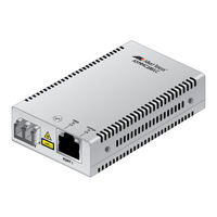
Allied Telesis AT-MMC200/ST Installation Manual (66 pages)
Mini Switching Media Converters
Brand: Allied Telesis
|
Category: Media Converter
|
Size: 9 MB
Table of Contents
Advertisement
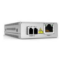
Allied Telesis AT-MMC200/ST Installation Manual (66 pages)
Mini Switching Media Converters
Brand: Allied Telesis
|
Category: Media Converter
|
Size: 3 MB