Table of Contents
Advertisement
Quick Links
Advertisement
Table of Contents

Subscribe to Our Youtube Channel
Related Manuals for Allied Telesis MCF3000 Series


Summary of Contents for Allied Telesis MCF3000 Series
- Page 1 MCF3000 Series Multi-channel Media Converters MCF3300 Chassis MCF3000/8LC Media Converter MCF3000/8SP Media Converter MCF3010T/4SP Media Converter MCF3000M Management Module MCF3300AC Power Supply MCF3300DC Power Supply Installation Guide 613-002756 Rev. A...
- Page 2 Allied Telesis, Inc. has been advised of, known, or should have known, the...
- Page 3 Electrical Safety and Emissions Standards This product meets the following standards. U.S. Federal Communications Commission Radiated Energy Note: This equipment has been tested and found to comply with the limits for a Class A digital device pursuant to Part 15 of FCC Rules.
- Page 4 Translated Safety Statements Important: Safety statements that have the symbol are translated into multiple languages in the Translated Safety Statements document at www.alliedtelesis.com/library. Remarque: Les consignes de sécurité portant le symbole sont traduites dans plusieurs langues dans le document Translated Safety Statements, disponible à l'adresse www.alliedtelesis.com/ library.
-
Page 5: Table Of Contents
Contents Preface ................................11 Document Conventions ............................ 12 Contacting Allied Telesis ..........................13 Chapter 1: Overview ............................15 Introduction............................... 16 MCF3300 Chassis ............................18 Media Converter Modules ..........................19 Media Converter Channels..........................21 MissingLink Mode............................. 23 Port Link LEDs ............................23 Port Link Status............................ - Page 6 Contents Unpacking the Optional MCF3000M Management Module ................59 Installing the Power Cord Retaining Clips......................61 Chapter 5: Installing Media Converter and Management Modules ............63 Installing Media Converter Modules........................64 Installing the MCF3000M Management Module ....................67 Installing a Power Supply..........................71 Chapter 6: Installing the Media Converter on a Table or Desktop ............
- Page 7 Figures Figure 1: Front and Rear Panels of the MCF3300 Chassis....................18 Figure 2: Media Converter Modules .............................19 Figure 3: Channel 1 on a Media Converter Module......................21 Figure 4: MCF3300AC and MCF3300DC Power Supplies....................25 Figure 5: Copper Port LEDs on the MCF3000/8LC and MCF3000/8SP Modules..............29 Figure 6: Fiber Optic Port LEDs on the MCF3000/8LC and MCF3000/8SP Modules ............30 Figure 7: Link and Activity LEDs on the Copper Ports on the MCF3010T/4SP Module ............33 Figure 8: Fiber Optic Port LEDs on the MCF3010T/4SP Module ..................34...
- Page 8 Figures Figure 50: Cabling the MGMT Port on the MCF3000M Management Module ..............89 Figure 51: Raising the Retaining Clip on the MCF3300AC Power Supply ................92 Figure 52: Connecting the AC Power Cord...........................92 Figure 53: Positioning the Power Cord Retaining Clip......................93 Figure 54: Connecting the Power Cord to an AC Power Source ..................93 Figure 55: DC Terminal Block...............................96 Figure 56: Stripped Wire ...............................96...
- Page 9 Tables Table 1: MCF3000 Product Family ............................16 Table 2: MCF3000 Media Converter Modules ........................20 Table 3: Link/Activity LEDs on the Copper Ports on the MCF3000/8LC and MCF3000/8SP Modules .......29 Table 4: Link/Activity LEDs for the Fiber Optic Ports on the MCF3000/8LC and MCF3000/8SP Modules ......31 Table 5: Copper Port LEDs on the MCF3010T/4SP Module ....................33 Table 6: Fiber Optic Port LEDs on the MCF3010T/4SP Module ..................34 Table 7: Link/Activity LED on the MGMT Port ........................42...
- Page 10 Tables...
-
Page 11: Preface
Preface This guide contains the installation instructions for the MCF3000 Multi- channel Media Converters. This preface contains the following sections: “Document Conventions” on page 12 “Contacting Allied Telesis” on page 13... -
Page 12: Document Conventions
Preface Document Conventions This document uses the following conventions: Note Notes provide additional information. Caution Cautions inform you that performing or omitting a specific action may result in equipment damage or loss of data. Warning Warnings inform you that performing or omitting a specific action may result in bodily injury. -
Page 13: Contacting Allied Telesis
MCF3000 Media Converter Installation Guide Contacting Allied Telesis If you need assistance with this product, you may contact Allied Telesis technical support by going to the Support & Services section of the Allied Telesis web site at www.alliedtelesis.com/support. You can find links for the following services on this page: ... - Page 14 Preface...
- Page 15 Chapter 1 Overview Here are the sections in this chapter: “Introduction” on page 16 “MCF3300 Chassis” on page 18 “Media Converter Modules” on page 19 “Media Converter Channels” on page 21 “MissingLink Mode” on page 23 ...
-
Page 16: Chapter 1: Overview
Chapter 1: Overview Introduction The MCF3000 product family of multi-channel media converters provides a simple and reliable way to consolidate large numbers of geographically separated Fast Ethernet, Gigabit Ethernet, or 10 Gigabit Ethernet networks into a central location, with fiber optic cables. The media converter modules feature up to eight channels that function as independent media converters for transferring network traffic between copper and fiber optic cables. - Page 17 MCF3000 Media Converter Installation Guide Table 1. MCF3000 Product Family (Continued) Component Description MCF3000/8LC Media converter module with eight channels. Each channel has one 10/100/ 1000Mbps copper port and one fixed 1000Mbps (1000Base-SX) fiber optic port with duplex LC connectors. The fiber optic ports have a maximum operating distance of 500 meters (1640 ft.) with 50/125µm multimode cable or 220 meters (722 ft.)
-
Page 18: Mcf3300 Chassis
Chapter 1: Overview MCF3300 Chassis The front and rear panels of the MCF3300 Chassis are shown in Figure 1. Three Slots for Media Converter Modules Slot for MCF3000M MCF3300 Power MCF3300 Power Management Module Supply Supply Figure 1. Front and Rear Panels of the MCF3300 Chassis... -
Page 19: Media Converter Modules
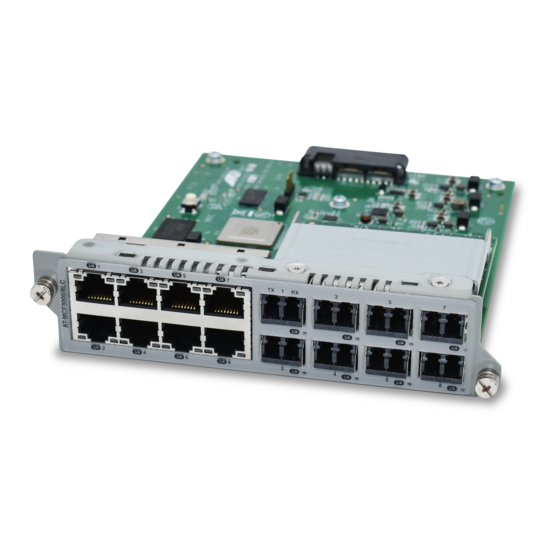
MCF3000 Media Converter Installation Guide Media Converter Modules The media converter modules are shown in Figure 2. MCF3000/8LC Eight 10/100/1000Mbps Eight 1000Mbps (1000Base- Copper Ports SX) Fiber Optic Ports with Duplex LC Connectors MCF3000/8SP Eight ports for 100Mbps Eight 10/100/1000Mbps (100Base-FX) or 1000Mbps Copper Ports (1000Base-SX/LX) SFP... -
Page 20: Table 2: Mcf3000 Media Converter Modules
Chapter 1: Overview The basic features of the media converter modules are listed in Table 2. Table 2. MCF3000 Media Converter Modules Media Fiber Optic Number of Maximum Maximum Converter Copper Ports Fixed Ports or Channels Distance Distance Module Transceivers MCF3000/8LC 10/100/ 100 meters... -
Page 21: Media Converter Channels
MCF3000 Media Converter Installation Guide Media Converter Channels The copper and fiber optic ports on the media converter modules are paired together, with each pair consisting of one copper port and one fiber optic port. Each pair functions as an independent media converter channel. - Page 22 Chapter 1: Overview The ports of a channel use store and forward to forward traffic. A packet is forwarded to the egress port of a channel after it has been fully received and buffered on the ingress port and checked for cyclic redundancy check (CRC) errors.
-
Page 23: Missinglink Mode
MCF3000 Media Converter Installation Guide MissingLink Mode The MissingLink mode is a feature of the channels on the media converter modules. It has two functions. It lets you use the port Link LEDs to quickly and easily identify which ports in a channel can establish links with their local or remote network device. -
Page 24: Guidelines
Chapter 1: Overview The value to this type of fault notification is that some network devices, such as managed Fast Ethernet switches, can respond to the loss of a link by performing a specific action. For example, the network device might send a trap to a network management station, and so alert the network administrator of the problem. -
Page 25: Power Supplies
MCF3000 Media Converter Installation Guide Power Supplies The power supplies for the chassis are the AC MCF3300AC and DC MCF3300DC modules. Refer to Figure 3. Figure 4. MCF3300AC and MCF3300DC Power Supplies Power supplies are installed in the two slots on the rear panel. Refer to Figure 1 on page 18. - Page 26 Chapter 1: Overview...
-
Page 27: Chapter 2: Media Converter Modules
Chapter 2 Media Converter Modules Here are the sections in this chapter: “MCF3000/8LC and MCF3000/8SP Media Converter Modules” on page 28 “MCF3010T/4SP Media Converter Module” on page 32... -
Page 28: Mcf3000/8Lc And Mcf3000/8Sp Media Converter Modules
Chapter 2: Media Converter Modules MCF3000/8LC and MCF3000/8SP Media Converter Modules Here are the properties of the copper and fiber optic ports on the MCF3000/8LC and MCF3000/8SP media converter modules: Media Converter The media converter channels are predefined. Channel 1 consists of copper port 1 and fiber optic port 1, channel 2 of copper port 2 and fiber Channels optic port 2, and so on. -
Page 29: Copper Port Leds
The media converter channel is operating in the MissingLink mode. The copper port has a link to a network device, but the fiber optic port in the channel does not. Refer to the MCF3000 Series Command Line Interface User Guide or MCF3000 Series Web Browser Interface User Guide. -
Page 30: Mcf3000/8Lc Fiber Optic Ports
Chapter 2: Media Converter Modules MCF3000/8LC The fiber optic ports on the MCF3000/8LC media converter module have the following properties: Fiber Optic Ports Fixed speed of 1Gbps (1000Base-SX) Full-duplex mode only Maximum operating distance of 500 meters (1640 ft.) with 50/ 125µm multimode fiber optic cable or 220 meters (722 ft.) with 62.5/125µm (core/cladding) multimode cable ... -
Page 31: Table 4: Link/Activity Leds For The Fiber Optic Ports On The Mcf3000/8Lc And Mcf3000/8Sp Modules
MissingLink mode. The fiber optic port has a link to a network device, but the companion copper port in the same channel does not. Refer to the MCF3000 Series Command Line Interface User Guide or MCF3000 Series Web Browser Interface User Guide. -
Page 32: Mcf3010T/4Sp Media Converter Module
Chapter 2: Media Converter Modules MCF3010T/4SP Media Converter Module Here are the properties of the copper and fiber optic ports on the MCF3010T/4SP media converter module: Media Converter The media converter channels are predefined. Channel 1 consists of copper port 1 and fiber optic port 1, channel 2 of copper port 2 and fiber Channels optic port 2, and so on. -
Page 33: Copper Port Leds
MissingLink mode. The copper port has a link to a network device, but the Link companion fiber optic port in the channel does not. Refer to the MCF3000 Series Command Line Interface User Guide or MCF3000 Series Web Browser Interface User Guide. -
Page 34: Fiber Optic Port Transceivers
MissingLink mode. The copper port has a link to a network device, but the Link companion fiber optic port in the channel does not. Refer to the MCF3000 Series Command Line Interface User Guide or MCF3000 Series Web Browser Interface User Guide. - Page 35 MCF3000 Media Converter Installation Guide Table 6. Fiber Optic Port LEDs on the MCF3010T/4SP Module (Continued) State Description Flashing Green The port is transmitting or receiving network traffic. Activity The port is not transmitting or receiving network traffic.
- Page 36 Chapter 2: Media Converter Modules...
-
Page 37: Chapter 3: Mcf3000M Management Module
Chapter 3 MCF3000M Management Module Here are the sections in this chapter: “Overview” on page 38 “Front Panel” on page 40 “MGMT Port” on page 41 “MGMT Port LEDs” on page 42 “CONSOLE Port” on page 43 ... -
Page 38: Overview
Chapter 3: MCF3000M Management Module Overview The optional MCF3000M management module is used to monitor and configure the ports and channels on the media converter modules. Refer to Figure 9. You can access the module locally through its CONSOLE port or remotely over your network through the MGMT 10/100/1000Base-T port, from Telnet or SSH clients. - Page 39 MCF3000 Media Converter Installation Guide Note For the complete list of management features, refer to the MCF3000 Series Command Line Interface User Guide or MCF3000 Series Web Browser Interface User Guide, available from the Allied Telesis web site.
-
Page 40: Front Panel
Chapter 3: MCF3000M Management Module Front Panel Figure 10 illustrates the front panel of the MCF3000M management module. Figure 10. Front Panel of the MCF3000M Management Module The front panel components are briefly described here: MGMT port - This is a standard 10/100/1000Base-T Ethernet port. The management module uses the port to communicate with your network when performing selected management functions, such as remote Telnet or Secure Shell (SSH) management and... -
Page 41: Mgmt Port
MCF3000 Media Converter Installation Guide MGMT Port The MGMT port is a standard Gigabit Ethernet port. You need to connect it to a device on your network, such as a Fast Ethernet or Gigabit Ethernet switch, if the management module will be performing any of the following management functions: ... -
Page 42: Mgmt Port Leds
Chapter 3: MCF3000M Management Module MGMT Port LEDs The 10/100/1000Base-T MGMT port has L/A (Link/Activity) LED. Unused Link/Activity Figure 11. Link/Activity LED on the Management Port The states of the Link/Activity LED are defined in Table 7. Table 7. Link/Activity LED on the MGMT Port State Description The port has not established a link to a network... -
Page 43: Console Port
Internet Protocol (IP) address because it is not conducted over a network. For instructions on how to start a local session, refer to “Starting a Local Management Session” on page 101 or the MCF3000 Series Command Line Interface User Guide. -
Page 44: Reset Button
Chapter 3: MCF3000M Management Module RESET Button The RESET button is used to restore the default settings to all system parameters. Here are situations where you might want to reset the module: Discard the current configuration and start over again with the default values. -
Page 45: Usb Port
Note The USB port cannot be used to upload or download configuration files from the management module. For instructions, refer to the MCF3000 Series Web Browser Interface User Guide or MCF3000 Series Command Line Interface User Guide. -
Page 46: Power And System Leds
Chapter 3: MCF3000M Management Module Power and System LEDs The Power and System LEDs on the right side of the panel display general status information. Refer to Figure 13. Power and System LEDs Figure 13. Power and System LEDs Table 8 defines the states of the LEDs. Table 8. -
Page 47: Chapter 4: Beginning The Installation
Chapter 4 Beginning the Installation The chapter contains the following sections: “Reviewing Safety Precautions” on page 48 “Choosing a Site for the Media Converter Chassis” on page 52 “Unpacking the MCF3300 Media Converter Chassis” on page 53 ... -
Page 48: Reviewing Safety Precautions
Chapter 4: Beginning the Installation Reviewing Safety Precautions Please review the following safety precautions before beginning the installation procedure. Note Safety statements that have the symbol are translated into multiple languages in the Translated Safety Statements document at www.alliedtelesis.com/library. Note Les consignes de sécurité... - Page 49 MCF3000 Media Converter Installation Guide Warning Power cord is used as a disconnection device. To de-energize equipment, disconnect the power cord. Warning Class I Equipment. This equipment must be earthed. The power plug must be connected to a properly wired earth ground socket outlet.
- Page 50 Use dedicated power circuits or power conditioners to supply reliable electrical power to the device. Caution The chassis may be heavy and awkward to lift. Allied Telesis recommends that you get assistance when mounting the chassis in an equipment rack.
- Page 51 MCF3000 Media Converter Installation Guide Caution The unit does not contain serviceable components. Please return damaged units for servicing. Warning The case temperature of operational fiber optic transceivers can exceed 40° C (158° F). Exercise caution when handling transceivers ...
-
Page 52: Choosing A Site For The Media Converter Chassis
Chapter 4: Beginning the Installation Choosing a Site for the Media Converter Chassis Observe these requirements when planning the installation of the media converter chassis. The device can be installed on a table or in a standard 19-inch equipment rack. ... -
Page 53: Unpacking The Mcf3300 Media Converter Chassis
MCF3000 Media Converter Installation Guide Unpacking the MCF3300 Media Converter Chassis The shipping box for the MCF3300 Media Converter Chassis is shown in Figure 14. Figure 14. MCF3300 Media Converter Chassis Shipping Box Figure 15 lists the items included in the MCF3300 Media Converter Chassis shipping box. -
Page 54: Figure 15: Items In The Mcf3300 Chassis Shipping Box
Chapter 4: Beginning the Installation One MCF3300 Chassis Two equipment rack brackets Eight bracket screws: Length: 6.0mm (0.2 in.) Diameter: 4.0mm (0.2 in.) Four bumper feet with rivets Figure 15. Items in the MCF3300 Chassis Shipping Box The items in Figure 16 are included if you purchased the chassis with the AC MCF3300AC Power Supply. -
Page 55: Figure 17: Front Panel
MCF3000 Media Converter Installation Guide Visually inspect the front panel for the pre-installed items in Figure 17. Three media converter module slot covers Figure 17. Front Panel Visually inspect the back panel. Figure 18 shows the pre-installed components for the chassis with the MCF3300AC Power Supply. One MCF3300AC Power Supply One management... -
Page 56: Figure 19: Pre-Installed Back Panel Components - Chassis And The Mcf3300Dc Power Supply
One power supply slot cover Figure 19. Pre-installed Back Panel Components - Chassis and the MCF3300DC Power Supply Note Please retain the original packaging material in the event you need to return the unit to Allied Telesis. -
Page 57: Unpacking The Mcf3300Ac Or Mcf3300Dc Power Supply
MCF3000 Media Converter Installation Guide Unpacking the MCF3300AC or MCF3300DC Power Supply The chassis comes with one pre-installed AC or DC power supply. A second power supply can be installed for power redundancy. Figure 20 shows the MCF3300AC Power Supply shipping box. Figure 20. -
Page 58: Figure 21: Mcf3300Dc Power Supply Shipping Box
Chapter 4: Beginning the Installation Figure 21 shows the MCF3300DC Power Supply shipping box. Figure 21. MCF3300DC Power Supply Shipping Box The contents include only the power supply. -
Page 59: Unpacking The Optional Mcf3000M Management Module
MCF3000 Media Converter Installation Guide Unpacking the Optional MCF3000M Management Module Figure 22 shows the MCF3000M Management Module shipping box. Figure 22. MCF3000M Management Module Shipping Box... -
Page 60: Figure 23: Items In The Mcf3000M Management Module Shipping Box
Chapter 4: Beginning the Installation Figure 23 lists the items included in the shipping box with the MCF3000M Management Module. One MCF3000M Management Module One management cable with micro USB and DB-9 (D-sub 9- pin) connectors Figure 23. Items in the MCF3000M Management Module Shipping Box... -
Page 61: Installing The Power Cord Retaining Clips
MCF3000 Media Converter Installation Guide Installing the Power Cord Retaining Clips The MCF3300AC Power Supply comes with a power cord retaining clip that protects the power cord from being accidentally unplugged from the unit. To install a power cord retaining clip, position the “u” part facing down, press in the sides, and insert the ends of the clip into the holes in the retaining bracket on the AC connector on the switch. - Page 62 Chapter 4: Beginning the Installation...
-
Page 63: Chapter 5: Installing Media Converter And Management Modules
Chapter 5 Installing Media Converter and Management Modules This chapter contains the following procedures: “Installing Media Converter Modules” on page 64 “Installing the MCF3000M Management Module” on page 67... -
Page 64: Installing Media Converter Modules
Chapter 5: Installing Media Converter and Management Modules Installing Media Converter Modules Note The media converter modules support hot swapping. You can install them while the chassis is powered on. Note There are no adjustable switches on the circuit boards of the media converter modules. -
Page 65: Figure 26: Sliding A Media Converter Module Into The Chassis
Note You should retain the packaging material in the event you need to return the unit to Allied Telesis. 4. Align the edges of the module with the guides in the slot and carefully slide the module into the chassis until it makes contact with the backplane connector in the chassis. -
Page 66: Figure 27: Seating A Media Converter Module On The Backplane Connector
Chapter 5: Installing Media Converter and Management Modules Figure 27. Seating a Media Converter Module on the Backplane Connector 6. Tighten the two captive screws on the media converter module with a cross-head screwdriver to secure it in the chassis. Refer to Figure 28. Figure 28. -
Page 67: Installing The Mcf3000M Management Module
MCF3000 Media Converter Installation Guide Installing the MCF3000M Management Module Note The MCF3000M Management Module supports hot-swapping. You can install it while the chassis is powered on. Caution The module is sensitive to and can be damaged by electrostatic discharge. Wear a grounding device and observe electrostatic discharge precautions when handling the module. -
Page 68: Figure 30: Removing The Battery Insulator From The Mcf3000M Management Module
Chapter 5: Installing Media Converter and Management Modules Battery Insulator Figure 30. Removing the Battery Insulator from the MCF3000M Management Module 4. Align the edges of the module with the card guides in the slot and carefully slide the module into the chassis until it makes contact with the connector on the backplane inside the chassis. -
Page 69: Figure 31: Installing The Management Module
MCF3000 Media Converter Installation Guide Card Guide Figure 31. Installing the Management Module 5. Gently press on both sides of the faceplate to seat the card on the connector on the backplane inside the chassis. Refer to Figure 32. Figure 32. Seating the MCF3000M Management Card on the backplane Connector 6. -
Page 70: Figure 33: Tightening The Captive Screws On The Mcf3000M Management Module
Chapter 5: Installing Media Converter and Management Modules Figure 33. Tightening the Captive Screws on the MCF3000M Management Module... -
Page 71: Installing A Power Supply
1. Unpack the MCF3300AC or MCF3300DC Power Supply from its shipping package and verify the package contents. Refer to “Unpacking the MCF3300AC or MCF3300DC Power Supply” on page 57. If any item is missing or damaged, contact your Allied Telesis sales representative for assistance. Note Please retain the original packaging material in the event you need to return the unit to Allied Telesis. -
Page 72: Figure 35: Removing The Blank Cover From A Power Supply Slot
Chapter 5: Installing Media Converter and Management Modules Figure 35. Removing the Blank Cover from a Power Supply Slot 4. Position the power supply as shown in Figure 36 and slide it into the slot until it makes contact with the connector inside the chassis. Figure 36. -
Page 73: Figure 37: Seating The Power Supply On The Connector In The Chassis
MCF3000 Media Converter Installation Guide Caution To prevent damaging the connector pins on the backplane, do not force the module into place. Figure 37. Seating the Power Supply on the Connector in the Chassis 6. Secure the power supply by tightening the two captive screws on the faceplate, with a cross-head screwdriver. - Page 74 Chapter 5: Installing Media Converter and Management Modules...
-
Page 75: Chapter 6: Installing The Media Converter On A Table Or Desktop
Chapter 6 Installing the Media Converter on a Table or Desktop This chapter contains the instructions for installing the media converter on a table or desktop. Warning Media converters should not be stacked on a table or desktop. They could present a physical safety hazard if you need to move or replace them. -
Page 76: Figure 40: Inserting The Rivet Housing Into The Bumper Foot
Chapter 6: Installing the Media Converter on a Table or Desktop 5. Install the bumper feet as follows: a. Insert a rivet housing into a bumper foot. Refer to Figure 40. Figure 40. Inserting the Rivet Housing into the Bumper Foot b. -
Page 77: Figure 42: Inserting The Rivet Into The Bumper Foot
MCF3000 Media Converter Installation Guide Figure 42. Inserting the Rivet into the Bumper Foot d. Repeat this step to install the remaining bumper feet. 6. Turn the switch over and place it on a flat, secure desk or table, leaving ample space around it for ventilation. - Page 78 Chapter 6: Installing the Media Converter on a Table or Desktop...
-
Page 79: Chapter 7: Installing The Mcf3300 Chassis In An Equipment Rack
Chapter 7 Installing the MCF3300 Chassis in an Equipment Rack This chapter contains the following procedures: “Removing the Bumper Feet” on page 80 “Installing the MCF3300 Chassis” on page 81... -
Page 80: Removing The Bumper Feet
Chapter 7: Installing the MCF3300 Chassis in an Equipment Rack Removing the Bumper Feet The bumper feet included with the media converter should not be used when installing the device in an equipment rack. If they are already installed, perform the following procedure to remove them: 1. -
Page 81: Installing The Mcf3300 Chassis
Please review the information and perform the procedures in Chapter 4, “Beginning the Installation” on page 47 before installing the switch. Caution The chassis may be heavy and awkward to lift. Allied Telesis recommends that you get assistance when mounting the chassis in an equipment rack. E28... -
Page 82: Figure 45: Installing The Mcf3300 Chassis In An Equipment Rack
Chapter 7: Installing the MCF3300 Chassis in an Equipment Rack 3. Mount the chassis in a 19-inch rack using standard screws (not provided). Refer to Figure 45. Figure 45. Installing the MCF3300 Chassis in an Equipment Rack... -
Page 83: Chapter 8: Cabling The Media Converter And Management Modules
Chapter 8 Cabling the Media Converter and Management Modules Here are the sections in this chapter: “Cabling Copper Ports” on page 84 “Installing SFP/SFP+ Transceivers” on page 85 “Cabling the MGMT Port on the MCF3000M Management Module” on page 89 Please review “Media Converter Channels”... -
Page 84: Cabling Copper Ports
Chapter 8: Cabling the Media Converter and Management Modules Cabling Copper Ports Here are the guidelines to cabling copper ports: The connectors on the cables should fit snugly into the ports, and the tabs should lock the connectors into place. ... -
Page 85: Installing Sfp/Sfp+ Transceivers
MCF3000/8SP and MCF3010/ 4SP modules, refer to the documents included with the transceivers. For a list of supported transceivers, refer to the product data sheet on the Allied Telesis web site. You should install transceivers in the media converter modules before connecting the fiber optic cables. -
Page 86: Installing Sfp/Sfp+ Transceivers
Chapter 8: Cabling the Media Converter and Management Modules Installing SFP/ To install fiber optic transceivers in MCF3000/8SP or MCF3010/4SP modules, perform the following procedure: SFP+ Transceivers Note The transceiver shown in the illustrations has a duplex LC connector. Your transceivers may have different connectors. 1. -
Page 87: Figure 47: Removing The Dust Cover From A Transceiver
MCF3000 Media Converter Installation Guide Note If you are ready to attach the fiber optic cable to the transceiver, continue with the next step. Otherwise, repeat this procedure to install other transceivers in the media converter modules. 7. Remove the dust cover from the transceiver. Refer to Figure 47 on page 87. -
Page 88: Figure 49: Connecting A Fiber Optic Cable To A Transceiver
Chapter 8: Cabling the Media Converter and Management Modules Figure 49. Connecting a Fiber Optic Cable to a Transceiver 10. Repeat this procedure to install additional transceivers. 11. After installing the transceivers, go to Chapter 9, “Powering On and Verifying the Chassis” on page 91. -
Page 89: Cabling The Mgmt Port On The Mcf3000M Management Module
Enhanced Category 5 (Cat 5e) unshielded cable. Note The management module must have an IP address to communicate with your network. For instructions, refer to the MCF3000 Series Web Browser Interface User Guide or MCF3000 Series Command Line Interface User Guide. - Page 90 Chapter 8: Cabling the Media Converter and Management Modules 2. Connect the other end of the cable to a 10Mbps, 100Mbps, or 1000Mbps port on a network device, such as an Ethernet switch or router.
-
Page 91: Chapter 9: Powering On And Verifying The Chassis
Chapter 9 Powering On and Verifying the Chassis This chapter contains the following procedures: “Powering On the MCF3300AC Power Supply” on page 92 “Powering On the MCF3300DC Power Supply” on page 95 “Verifying the Media Converter” on page 100 ... -
Page 92: Powering On The Mcf3300Ac Power Supply
Chapter 9: Powering On and Verifying the Chassis Powering On the MCF3300AC Power Supply To power on MCF3300AC power supplies, perform the following procedure: 1. Raise the retaining clip to the upright position on the MCF3300AC Power Supply. Figure 51. Raising the Retaining Clip on the MCF3300AC Power Supply 2. -
Page 93: Figure 53: Positioning The Power Cord Retaining Clip
MCF3000 Media Converter Installation Guide 3. Lower the power cord retaining clip to secure the power cord to the chassis. Figure 53. Positioning the Power Cord Retaining Clip 4. Plug the other end of the power cord into an appropriate power source. Refer to Figure 54. - Page 94 Chapter 9: Powering On and Verifying the Chassis Note The unit might have more than one power source. To reduce the risk of electric shock, disconnect all power cords before servicing the unit. E30 For instructions on how to verify the operations of the modules, go to “Verifying the Media Converter”...
-
Page 95: Powering On The Mcf3300Dc Power Supply
MCF3000 Media Converter Installation Guide Powering On the MCF3300DC Power Supply This section contains the procedure for wiring the DC connector on the MCF3300DC power supply. Warning As a safety precaution, install a circuit breaker with a minimum value of 15 Amps between the equipment and the DC power source. ... -
Page 96: Figure 55: Dc Terminal Block
Chapter 9: Powering On and Verifying the Chassis 2. Use the legend above the terminal block to identify the terminals. The terminals are positive, power supply ground and negative, from left to right, as shown in Figure 55. Ground +48 VDC Positive -48 VDC Negative Terminal Terminal... -
Page 97: Figure 58: Loosening The Ground Screw On The Mcf3300Dc Power Supply
MCF3000 Media Converter Installation Guide Note Allied Telesis recommends tinning the wires with solder to protect against loose strands. This guide does not contain instructions on how to tin wires. 5. Loosen the retaining screw to the Ground connector on the power supply with a #1 flathead screwdriver. -
Page 98: Figure 59: Connecting The Ground Wire To The Dc Terminal Block
Chapter 9: Powering On and Verifying the Chassis Figure 59. Connecting the Ground Wire to the DC Terminal Block 7. Repeat steps 5 and 6 to connect the +48 VDC (RTN) feed wire to the terminal block marked + (plus). 8. - Page 99 MCF3000 Media Converter Installation Guide 10. Secure the tray cable near the rack framework using multiple cable ties to minimize the chance of the connections being disturbed by casual contact with the wiring. Use at least four cable ties, separated four inches apart.
-
Page 100: Verifying The Media Converter
Chapter 9: Powering On and Verifying the Chassis Verifying the Media Converter The instructions in this chapter are used to verify the proper operations of the modules and should be performed after the initial installation of the media converter or whenever you add or replace modules. The sections are listed here: ... -
Page 101: Starting A Local Management Session
The management module comes with the default IP address 192.168.1.1. For instructions on remote management sessions, refer to the MCF3000 Series Web Browser Interface User Guide or MCF3000 Series Command Line Interface User Guide. To start a local management session on the MCF3000M Management Module: 1. -
Page 102: Figure 62: Connecting The Usb Cable To Your Computer
Chapter 9: Powering On and Verifying the Chassis Figure 62. Connecting the USB Cable to Your Computer 3. Configure the terminal or terminal emulator program as follows: Baud rate: 115200 bps (The baud rate of the RS-232 Terminal port is adjustable from 9600 to 115200 bps. - Page 103 The management session starts and the command line interface prompt is displayed: MCF3000>> 7. To display a list of commands, press the Return key or type a question mark “?”: MCF3000>>? For more information, refer to the r MCF3000 Series Command Line Interface User Guide.
- Page 104 Chapter 9: Powering On and Verifying the Chassis...
-
Page 105: Chapter 10: Replacing Modules
Chapter 10 Replacing Modules This chapter contains the following procedures: “Replacing Media Converter Modules” on page 106 “Removing the MCF3300AC Power Supply” on page 109 “Removing the MCF3300DC Power Supply” on page 113 “Replacing the MCF3000M Management Module” on page 116... -
Page 106: Replacing Media Converter Modules
Chapter 10: Replacing Modules Replacing Media Converter Modules Caution Media converter modules are sensitive to and can be damaged by electrostatic discharge. Wear a grounding device and observe electrostatic discharge precautions when handling the modules. To remove a media converter module: 1. -
Page 107: Figure 64: Sliding The Media Converter Module From The Chassis
For further information, refer to the MCF3000 Series Command Line Interface User Guide or MCF3000 Series Web Browser Interface User Guide. 7. If you are not installing a new module, position the slot cover and secure it by tightening the two captive screws. -
Page 108: Figure 65: Installing The Slot Cover Over A Media Converter Slot
Chapter 10: Replacing Modules Figure 65. Installing the Slot Cover over a Media Converter Slot... -
Page 109: Removing The Mcf3300Ac Power Supply
MCF3000 Media Converter Installation Guide Removing the MCF3300AC Power Supply This section contains the procedure for removing the MCF3300AC Power Supply from the chassis. The power supply is hot-swappable. You do not have to power off the chassis to install or remove a power supply in a chassis that has two power supplies. -
Page 110: Figure 68: Disconnecting The Power Cord From The Mcf3300Ac Power Supply
Chapter 10: Replacing Modules 3. Disconnect the power cord from the chassis. Refer to Figure 68. Figure 68. Disconnecting the Power Cord from the MCF3300AC Power Supply 4. Using a cross-head screwdriver, loosen the two captive screws on the power supply. Refer to Figure 69. Figure 69. -
Page 111: Figure 70: Pulling On The Handle To Disconnect The Mcf3300Ac Power Supply From The Chassis
MCF3000 Media Converter Installation Guide Figure 70. Pulling on the Handle to Disconnect the MCF3300AC Power Supply from the Chassis 6. Slide the power supply out from the chassis. Refer to Figure 71. Caution The power supply is heavy. Hold it with both hands when removing it from the chassis. -
Page 112: Figure 72: Installing The Blank Cover On The Power Supply Slot
Chapter 10: Replacing Modules 7. To install a replacement power supply, refer to “Installing a Power Supply” on page 71. 8. If you are not installing a replacement power supply now, install the blank slot cover. Refer to Figure 72. Figure 72. -
Page 113: Removing The Mcf3300Dc Power Supply
MCF3000 Media Converter Installation Guide Removing the MCF3300DC Power Supply This section contains the procedure for removing the MCF3300DC Power Supply from the chassis. The power supply is hot-swappable. You do not have to power off the chassis to install or remove a power supply in a chassis that has two power supplies. -
Page 114: Figure 74: Loosening The Two Captive Screws On The Mcf3300Dc Power Supply
Chapter 10: Replacing Modules Warning When installing or removing this equipment, always connect the power supply ground connection first and disconnect it last. E11 5. Using a cross-head screwdriver, loosen the two captive screws on the power supply. Refer to Figure 74. Figure 74. -
Page 115: Figure 76: Sliding The Mcf3300Dc Power Supply From The Chassis
MCF3000 Media Converter Installation Guide Caution The power supply is heavy. Use both hands to remove it from the chassis. Figure 76. Sliding the MCF3300DC Power Supply from the Chassis 8. To install a replacement power supply, refer to “Installing a Power Supply”... -
Page 116: Replacing The Mcf3000M Management Module
If you do not have a backup copy of the configuration file from the current management module and if the module is still operational, you should create a backup copy before replacing it. Refer to the MCF3000 Series Command Line Interface User Guide or MCF3000 Series Web Browser Interface User Guide. ... -
Page 117: Figure 77: Disconnecting Cables And Usb Device From The Mcf3000M Module
MCF3000 Media Converter Installation Guide Figure 77. Disconnecting Cables and USB Device from the MCF3000M Module 2. Loosen the two captive screws on the management modules with a cross-head screwdriver. Refer to Figure 78. Figure 78. Loosening the Captive Screws on the MCF3000M Management Module 3. -
Page 118: Figure 79: Disconnecting The Mcf3000M Management Module From The Backplane Connector
Chapter 10: Replacing Modules Figure 79. Disconnecting the MCF3000M Management Module from the Backplane Connector 4. Slide the module from the chassis. Refer to Figure 80. Figure 80. Removing the MCF3000M Management Module from the MCF3300 Chassis 5. If you are not immediately installing the management module in another chassis, store it in an anti-static bag. -
Page 119: Figure 81: Installing The Blank Management Slot Cover
To install a replacement module, refer to “Installing the MCF3000M Management Module” on page 67. After installing the replacement module, download the most recent backup configuration file to it. Refer to the MCF3000 Series Command Line Interface User Guide or MCF3000 Series Web Browser Interface User Guide. ... - Page 120 Chapter 10: Replacing Modules...
-
Page 121: Chapter 11: Troubleshooting
Chapter 11 Troubleshooting The following sections contain troubleshooting recommendations should you encounter a problem with the product: “Media Converter Modules” on page 122 “MCF3300AC Power Supply Module” on page 126 “MCF3300DC Power Supply Module” on page 127 ... -
Page 122: Media Converter Modules
Chapter 11: Troubleshooting Media Converter Modules Problem: All the port LEDs on a media converter module are off. Solution: Try the following: Visually inspect the module to be sure that it is fully installed in the slot. If the chassis has the MCF3000M management module, check the Power and System LEDs. - Page 123 MCF3000 Media Converter Installation Guide Problem: The Link/Activity LED of a fiber optic port is off. Solution: The fiber optic port is unable to establish a link to the remote network device. Try the following: Verify that the remote network device connected to the fiber optic port is operating properly.
- Page 124 Chapter 11: Troubleshooting Problem: A port’s Link/Activity LED is slowly blinking once a second. Solution: This means that the media converter channel is operating in the MissingLink mode. The port with the blinking LED can establish a link with its network device, but the companion port in the same channel cannot establish a link, If the companion port is a copper port, refer to Problem 2.
- Page 125 MCF3000 Media Converter Installation Guide Another possible cause is an intermittent link on a port, perhaps because of a problem with a cable or a network device. To identify which port has the problem, set the channel to the regular mode and go to the previous Problem.
-
Page 126: Mcf3300Ac Power Supply Module
Chapter 11: Troubleshooting MCF3300AC Power Supply Module Problem: The fans in the power supply have stopped. Solution: The power supply module is not receiving power or has a technical problem. Try the following: Verify that the module is fully seated in the power supply slot in the chassis. -
Page 127: Mcf3300Dc Power Supply Module
MCF3000 Media Converter Installation Guide MCF3300DC Power Supply Module Problem: The fans in the power supply have stopped. Solution: The power supply module is not receiving power or has a technical problem. Try the following: Verify that the module is fully seated in the power supply slot in the chassis. -
Page 128: Mcf3000M Management Module
Chapter 11: Troubleshooting MCF3000M Management Module Problem: The POWER and SYSTEM LEDs on the module are off. Solution: Try the following: Verify that the power supply module in the chassis is operating properly. Refer to “MCF3300AC Power Supply Module” on page 126. - Page 129 Start a local management session on the management module and verify that it has an IP address configuration. Refer to the MCF3000 Series Command Line Interface User Guide. If your workstation and the management module are members of different networks, verify that the IP address configuration on the module includes a default gateway.
- Page 130 Chapter 11: Troubleshooting...
-
Page 131: Appendix A: Technical Specifications
Appendix A Technical Specifications This appendix contains the following sections: ”Physical Specifications” on page 132 ”Environmental Specifications” on page 134 ”Power Specifications” on page 135 ”Certifications” on page 137 ”RJ-45 Copper Port Pinouts” on page 138 ... -
Page 132: Physical Specifications
Appendix A: Technical Specifications Physical Specifications Dimensions (H x W x D) Table 9 and Figure 83 list the product dimensions. Table 9. Product Dimensions MCF3300 Chassis 4.3 cm x 44.0 cm x 43.7 cm (1.7 in. x 17.3 in. x 17.2 in.) MCF3000/8LC Module 3.6 cm x 14.5 cm x 16.5 cm MCF3000/8SP Module... -
Page 133: Figure 84: Bracket Hole Locations
MCF3000 Media Converter Installation Guide Figure 84 shows the locations of the bracket holes on the sides of the media converter. 30.48 mm (1.20 in.) 6.60 mm (0.26 in.) 42.67 mm 93.98 mm (1.68 in.) (3.70 in.) Figure 84. Bracket Hole Locations Weights Table 10 lists the product weights. -
Page 134: Environmental Specifications
Appendix A: Technical Specifications Environmental Specifications Table 12 lists the environmental specifications of the switches. sb - from Table 12. Environmental Specifications Operating Temperature 0° C to 50° C (32° F to 122° F) Storage Temperature -15° C to 65° C (-5° F to 149° F) Operating Humidity 5% to 95% noncondensing Storage Humidity... -
Page 135: Power Specifications
MCF3000 Media Converter Installation Guide Power Specifications This section contains the maximum power consumption values and input voltages. Maximum Power Consumption Table 13 list the maximum power consumption. Table 13. Maximum Power Consumption (Watts) MCF3300 Chassis 100W MCF3000/8LC Module MCF3000/8SP Module MCF3010T/4SP Module MCF3000M Module Input Voltage... - Page 136 Appendix A: Technical Specifications Table 16. Heat Dissipations (British Thermal Units/Hour) (Continued) MCF3000/8SP Module 71.61 BTU/hr MCF3010T/4SP Module 102.30 BTU/hr MCF3000M Module 23.87 BTU/hr MCF3300AC Power Supply 8.67 BTU/hr = 2.54W MCF3300DC Power Supply 8.67 BTU/hr = 2.54W...
-
Page 137: Certifications
MCF3000 Media Converter Installation Guide Certifications Table 17 lists the product certificates. Table 17. Product Certifications Safety UL62368-1 CAS C22.2 No. 62368-1 EN62368-1, CE Mark EMI (Emissions) FCC Class A EN55022 Class A VCCI Class A ICES EMC (Immunity) EN55024 Electrical and Laser Safety EN62368-1 (TUV), UL62368-1 ), EN60825... -
Page 138: Copper Port Pinouts
Appendix A: Technical Specifications RJ-45 Copper Port Pinouts Figure 85 illustrates the pin layout of the RJ-45 connectors on the media converter modules and the MGMT port on the MCF3000M module. Figure 85. Pin Layout (Front View) of the RJ-45 Connectors Table 18 lists the pin signals for 10 or 100Mbps. - Page 139 MCF3000 Media Converter Installation Guide Table 19. Pin Signals on Copper Ports at 1000Mbps (Continued) TX and RX+ TX and RX- TX and RX- TX and RX+ TX and RX-...
-
Page 140: Micro-Usb Console Port Pinouts
Appendix A: Technical Specifications Micro-USB Console Port Pinouts Table 20 lists the pin signals on the micro-USB Console port on the MCF3000M management module. sb - need to verify Table 20. Micro-USB Console Port Pin Signals Signal USB2 VBUS Input USB2 Data Negative USB2 Data Positive Not Connected... -
Page 141: Fiber Optic Ports On The Mcf3000/8Lc Module
MCF3000 Media Converter Installation Guide Fiber Optic Ports on the MCF3000/8LC Module Table 21 lists the specifications for the 1000Base-FX fiber optic ports on the MCF3000/8LC Module. sb - done Table 21. Specifications for the Fiber Optic Ports on the MCF3000/8LC Module General Connector... - Page 142 Appendix A: Technical Specifications...
Need help?
Do you have a question about the MCF3000 Series and is the answer not in the manual?
Questions and answers