
Related Manuals for Allied Telesis MMC10G Series


Summary of Contents for Allied Telesis MMC10G Series
-
Page 1: Installation Guide
MMC10G Series Layer 1 Mini Media Converters MMC10GSP/SP MMC10GT/SP Installation Guide 613-002801 Rev A... - Page 2 Allied Telesis, Inc. has been advised of, known, or should have known, the...
-
Page 3: Industry Canada
Electrical Safety and Emissions Standards This section contains the following: “US Federal Communications Commission” “Industry Canada” “Emissions, Immunity and Electrical Safety Standards” on page 4 “Translated Safety Statements” on page 4 US Federal Communications Commission Radiated Energy Note This equipment has been tested and found to comply with the limits for a Class A digital device pursuant to Part 15 of FCC Rules. - Page 4 Emissions, Immunity and Electrical Safety Standards RFI Emissions FCC Class A, EN55032 Class A, CISPR 32 Class A, VCCI Class A, RCM Warning In a domestic environment this product may cause radio interference in which case the user may be required to take adequate measures. ...
-
Page 5: Table Of Contents
Contents Preface................................11 Symbol Conventions ..........................12 Contacting Allied Telesis..........................13 Chapter 1 : Overview ............................. 15 Introduction ..............................16 Front and Back Panels..........................17 Port Specifications ............................. 18 Features ..............................19 Twisted-Pair Port ..........................20 Auto-Negotiation or Full-Duplex ......................20 Auto MDI/MDI-X .......................... - Page 6 Contents Cabling Guidelines ..........................56 Applying Power and Connecting the Network Cables................56 Chapter 5 : Troubleshooting ........................... 59 Appendix A: Technical Specifications ......................63 Physical Specifications ..........................63 Environmental Specifications ........................64 Power Specifications ..........................64 Safety and Electromagnetic Emissions Certifications ................64 RJ45 Connector and Port Pinouts ......................
- Page 7 Figure 24: Inserting the SFP..............................54 Figure 25: Positioning the SFP Handle in the Upright Position ................... 55 Figure 26: Connecting 12VDC Powered Unit ........................56 Figure 27: MMC10G Series Dimensions ..........................63 Figure 28: RJ45 Connector and Port Pin Layout ......................... 65...
- Page 8 List of Figures...
- Page 9 Tables Table 1. Port Specifications for the MMC10GSP/SP ......................18 Table 2. Port Specifications for the MMC10GT/SP ......................18 Table 3. PWR and SYS LEDs on the Back Panel ......................23 Table 4. Port LEDs for the MMC10GT/SP ..........................24 Table 5. Port LEDs for the MMC10GSP/SP Model ......................25 Table 6.
- Page 10 List of Tables...
-
Page 11: Preface
Preface This preface contains the following sections: “Symbol Conventions” on page 12 “Contacting Allied Telesis” on page 13 This guide contains the installation instructions for the following Layer 1 Mini Media Converters. MMC10GSP/SP MMC10GT/SP ... -
Page 12: Symbol Conventions
Symbol Conventions This document uses the following conventions: Note Notes provide additional information. Caution Cautions inform you that performing or omitting a specific action may result in equipment damage or loss of data. Warning Warnings inform you that performing or omitting a specific action may result in bodily injury. -
Page 13: Contacting Allied Telesis
MMC10G Series Mini Media Converter Installation Guide Contacting Allied Telesis If you need assistance with this product, you may contact Allied Telesis technical support by going to the Support & Services section of the Allied Telesis web site at www.alliedtelesis.com/support. You can find links for... -
Page 15: Chapter 1 : Overview
Chapter 1 Overview This chapter contains the following sections: “Introduction” on page 16 “Front and Back Panels” on page 17 “Port Specifications” on page 18 “Features” on page 19 “LED Modes” on page 27 “External AC/DC Power Adapter” on page 32 ... -
Page 16: Introduction
Chapter 1: Overview Introduction The MMC10G Series Mini Media Converters extend the distance of your network by interconnecting LAN devices that are physically separated by large distances. The MMC10G Series Mini Media Converters include the following models: MMC10GSP/SP MMC10GT/SP ... -
Page 17: Front And Back Panels
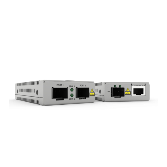
1 Gbps or 10 Gbps 1 Gbps or 10 Gbps SFP+ Port SFP+ Port Figure 2. MMC10GSP/SP Front Panel Figure 3 illustrates the back panel of the MMC10G Series Media Converter. SML ON/OFF 12 VDC Input DIP Switch PWR LED... -
Page 18: Port Specifications
Chapter 1: Overview Port Specifications The MMC10GSP/SP Media Converter allows enterprises to connect fiber networks to fiber networks, offering a cost-effective method for integrating fiber-optic cabling into 1Gbps SFP or 10Gbps SFP+. See Table 1 for the port specifications of the MMC10GSP/SP Media Converter. Table 1. -
Page 19: Features
MMC10G Series Mini Media Converter Installation Guide Features Here are the key features of the MMC10G Series Media Converters: 10G copper cabling up to 100m with CAT6A MMC10GSP/SP supports two SFP+ ports MMC10GT/SP supports one SFP+ port and one copper RJ45 port ... -
Page 20: Twisted-Pair Port
MMC10G. As it receives its original test packets, it checks for lost packets and packets with errors, and displays the results in statistic counters. Figure 4 on page 21 shows a successful test, using an Allied Telesis switch as the link partner. -
Page 21: Figure 4: Loopback Test For Mmc10Gt/Sp
MMC10G Series Mini Media Converter Installation Guide Figure 4. Loopback Test for MMC10GT/SP A successful test verifies that the number of packets received equals the number of packets sent. If the numbers do not match, try restarting the media converter, making sure that the cables are connected properly or... -
Page 22: Leds
Chapter 1: Overview Note Loopback tests only work for fiber optic ports, you cannot test a copper port. Additionally, the fiber cable connectivity can only be tested using the SFP+ 10Gbps transmitter. It cannot be tested with SFP 1Gbps transmitter. To use Loopback Mode, set the LPBK DIP switch on the back panel to ON. -
Page 23: Mmc10Gt/Sp Front Panel
MMC10G Series Mini Media Converter Installation Guide Table 3 describes the media converter LEDs on the back panel. Table 3. PWR and SYS LEDs on the Back Panel State Description The media converter is not receiving power. Steady Green The media converter is receiving power. -
Page 24: Table 4. Port Leds For The Mmc10Gt/Sp
Chapter 1: Overview Table 4 describes the port LEDs on the front panel of the MMC10GT/SP Media Converter. Table 4. Port LEDs for the MMC10GT/SP State Description The port has not established a link. Steady Green The port has a 10G link to a network device. Port 1 Copper Steady Amber... -
Page 25: Mmc10Gsp/Sp Front Panel
MMC10G Series Mini Media Converter Installation Guide MMC10GSP/SP Front Panel Figure 7 shows the port LEDs on the MMC10GSP/SP Media Converter. Link/Activity 1 Link/Activity 2 Figure 7. Port LEDs on the MMC10GSP/SP Model Table 5 describes the port LEDs on the MMC10GSP/SP model. -
Page 26: Table 6. Dip Switches For The Mmc10Gt/Sp Model
Chapter 1: Overview Table 6 describes the functions of the MMC10GT/SP DIP switches. Table 6. DIP Switches for the MMC10GT/SP Model LPBK Description Down Down Normal operation (no missing link) Down Smart MissingLink mode enabled Down Loopback mode enabled Packet generation enabled (MMC10GT/SP only) Table 7 describes the functions of the MMC10GSP/SP DIP switches. -
Page 27: Led Modes
MMC10G Series Mini Media Converter Installation Guide LED Modes The ports have LEDs that display link status and traffic activity. The LEDs have two modes: Regular mode Smart MissingLink mode Normal Mode The Link/Activity LEDs on the media converter DIP switch set to the normal mode (i.e., SML and Loopback Mode are not switched on) display... -
Page 28: Sml Example Scenarios In Normal Condition
Chapter 1: Overview If the failure had started with the fiber-optic cabling (as shown in Figure 12 on page 29), then the copper Port 1 Link LED would blink slowly, and the fiber Port 2 Link LED would turn OFF. SML Example Scenarios in Normal Condition Following are example scenarios with SML-enabled media converters. -
Page 29: Sml Example Scenarios With Connection Down In One Media Converter Configuration
MMC10G Series Mini Media Converter Installation Guide SML Example Scenarios with Connection Down in One Media Converter Configuration Figure 11 shows a media converter and end node Link LED behavior with SML enabled with a copper connection down. MMC10GT/SP End Node... -
Page 30: Sml Example Scenarios With Connection Down In Two Media Converters Configuration
Chapter 1: Overview SML Example Scenarios with Connection Down in Two Media Converters Configuration Following are example scenarios with two SML enabled media converters connected back-to-back (bookend mode). Figure 13 shows media converter and end node Link LED behavior with SML enabled with a copper connection down between a media converter and an end node. -
Page 31: Enabling Sml
MMC10G Series Mini Media Converter Installation Guide Enabling SML To enable SML on the unit, set the SML ON/OFF DIP switch on the rear panel of the unit to the ON (up) position. See Figure 15. Loopback ON/OFF SML ON/OFF Figure 15. -
Page 32: External Ac/Dc Power Adapter
Chapter 1: Overview External AC/DC Power Adapter The media converter comes with a UL-approved safety compliant AC power adapter for 120 and 240 VAC environments, with a regulated output of 12 VDC. The power required for the media converter is 12 VDC, 350 mA. -
Page 33: Resetting The Media Converter
MMC10G Series Mini Media Converter Installation Guide Resetting the Media Converter You may have to power cycle the media converter when entering or exiting loopback or packet generation mode. If so, reset the media converter by powering OFF then powering ON the unit. - Page 34 Chapter 1: Overview...
-
Page 35: Chapter 2 : Beginning The Installation
Chapter 2 Beginning the Installation This chapter contains the following sections: “Reviewing Safety Precautions” on page 36 “Selecting a Site for the Media Converter” on page 38 “Planning the Installation” on page 39 “Unpacking the Media Converter” on page 41 ... -
Page 36: Reviewing Safety Precautions
available in a PDF document titled Translated Safety Statements on the Allied Telesis website at www.alliedtelesis.com/support. Caution Air vents must not be blocked and must have free access to the room ambient air for cooling. - Page 37 MMC10G Series Mini Media Converter Installation Guide Caution Failing to pick up the ferrule tip when you reach the bottom of the cleaning surface can result in static electricity that can damage the fiber-optic cable. Warning In a domestic environment this product may cause radio interference in which case the user may be required to take adequate measures.
-
Page 38: Selecting A Site For The Media Converter
Chapter 2: Beginning the Installation Selecting a Site for the Media Converter Observe the following requirements when choosing a site for your media converter: If you are installing the media converter on a table, verify that the table is level and secure. The power outlet for the media converter should be located near ... -
Page 39: Planning The Installation
1Gbps and 10Gbps modules are supported. Note For the MMC10G Series Media Converters, you must purchase the SFP+ transceiver separately. The maximum operating distance of the MMC10G Series Media Converter is dependent on the specific SFP+ module. For a list of supported transceivers, contact your Allied Telesis distributor or reseller. - Page 40 Chapter 2: Beginning the Installation Note The twisted-pair port on the MMC10GT/SP Media Converter features Auto MDI/MDI-X when operating at 1Gbps and 10Gbps. The port is configured as MDI or MDI-X when it is connected to an end node. Consequently, you can use a straight-through twisted-pair cable when connecting any type of network device to the twisted- pair port on the media converter.
-
Page 41: Unpacking The Media Converter
MMC10G Series Mini Media Converter Installation Guide Unpacking the Media Converter To unpack the media converter, perform the following procedure: 1. Remove all of the components from the shipping package. Note Store the packaging material in a safe location. You must use the original shipping material if you need to return the unit to Allied Telesis. -
Page 42: Supported Accessories
Chapter 2: Beginning the Installation Supported Accessories MMCWLMT The MMCWLMT Wall Mount Kit is used for wall mounting. For installation instructions see “MMCWLMT Kit Installation” on page 48. Wall Mount Kit Figure 17. MMCWLMT Kit with Brackets MMCR18 The MMCR18 Chassis Kit is used as a power chassis. The MMCR18 rack-mount chassis provides rack-mount or desktop installation for up to Chassis Kit 18 MMC Series Media Converters. -
Page 43: Mmctray6 Tray
MMC10G Series Mini Media Converter Installation Guide Note The MMCR18 can support up to 12 MMC10G units with fiber SFP+ modules. The MMCR18 cannot support 18 MMC10G units, because of the higher power draw of the MMC10G compared to the MMC2000. - Page 44 Chapter 2: Beginning the Installation...
- Page 45 Chapter 3 Installation This chapter contains the following sections: “Installation Options” on page 46 “Desktop Installation” on page 47 “MMCWLMT Kit Installation” on page 48 ...
-
Page 46: Chapter 3: Installation
Note To install the media converter on a wall, you must purchase the MMCWLMT Kit separately. To install the media converter in a rack, see Allied Telesis’ AT- MMCR18 Media Converter Rack-mount Chassis Installation Guide. For another option to install the media converter in a rack, see Allied Telesis’... -
Page 47: Desktop Installation
MMC10G Series Mini Media Converter Installation Guide Desktop Installation To install the media converter on a desktop, perform the following procedure: 1. Place the media converter upside down on a flat, secure surface (such as a desk or table). 2. Affix the four adhesive rubber feet on the bottom of the media converter, one on each corner. -
Page 48: Mmcwlmt Kit Installation
Chapter 3: Installation MMCWLMT Kit Installation Before installing an MMC10G Series Media Converter on a wall, you must have an MMCWLMT Kit that is provided separately. 1. Verify that the MMCWLMT Kit contains the items shown in Table 9. MMCWLMT Kit Contents... -
Page 49: Figure 20: Attaching The Brackets To The Media Converter
MMC10G Series Mini Media Converter Installation Guide 4. Orient the brackets against the sides of the unit, as shown in Figure 20, and secure them to the unit with the four of the brackets screws included. Figure 20. Attaching the Brackets to the Media Converter 5. -
Page 50: Figure 22: Placing The Template On The Wall
Chapter 3: Installation 6. Use scotch tape to attach the template on the wall. 7. Pre-drill four 3/16” (5mm) holes at the locations on the template as shown in Figure 22. Figure 22. Placing the Template on the Wall 8. Remove the template from the wall. 9. -
Page 51: Figure 23: Securing The Media Converter To The Wall
MMC10G Series Mini Media Converter Installation Guide Figure 23. Securing the Media Converter to the Wall 11. Go to “Installing the SFP Transceiver” on page 54. - Page 52 Chapter 3: Installation...
-
Page 53: Chapter 4 : Powering On And Cabling The Media Converter
Chapter 4 Powering On and Cabling the Media Converter This chapter contains the following sections: “Installing the SFP Transceiver” on page 54 “Powering On and Cabling the Media Converter” on page 56 ... -
Page 54: Installing The Sfp Transceiver
Chapter 4: Powering On and Cabling the Media Converter Installing the SFP Transceiver To install an SFP transceiver, perform the following procedure: Note The transceiver can be hot-swapped; you do not need to power off the media converter to install a transceiver. However, always remove the cable before removing the transceiver. -
Page 55: Figure 25: Positioning The Sfp Handle In The Upright Position
MMC10G Series Mini Media Converter Installation Guide 3. Verify that the handle on the transceiver is in the upright position, as shown in Figure 25. This secures the transceiver and prevents it from being dislodged from the port. SFP Transceiver Handle Figure 25. -
Page 56: Powering On And Cabling The Media Converter
Chapter 4: Powering On and Cabling the Media Converter Powering On and Cabling the Media Converter Cabling Observe the following guidelines when connecting twisted-pair and fiber- optic cables to the ports on the media converter: Guidelines The connector on the cable should fit snugly into the port on the ... - Page 57 MMC10G Series Mini Media Converter Installation Guide 2. Plug the power adapter to a power outlet. Refer to “Power Specifications” on page 64 for power requirements. 3. Verify that the PWR LED is lit green. If the PWR LED is off, refer to “Troubleshooting”...
- Page 58 Chapter 4: Powering On and Cabling the Media Converter...
-
Page 59: Chapter 5 : Troubleshooting
This chapter contains information on how to troubleshoot the media converter if a problem occurs. Note For further assistance, please contact Allied Telesis Technical Support at www.alliedtelesis.com/support. Problem 1: The PWR LED on the media converter is off. Solutions: The unit is not receiving power. Try the following: Verify that the power cord is securely connected to the power ... - Page 60 Chapter 5: Troubleshooting Problem 4: The twisted-pair Port 1 on the MMC10GT Media Converter is connected to an end node, but the port’s copper Port 1 LINK LED is off. Solutions: The port is unable to establish a link to an end node. Try the following: Verify that the end node connected to the twisted-pair port is ...
- Page 61 MMC10G Series Mini Media Converter Installation Guide Verify that the operating specifications and wave lengths of the fiber-optic port on the SFP+ transceiver and the remote end-node are compatible. Verify that the correct type of fiber-optic cabling is being used.
- Page 62 Chapter 5: Troubleshooting...
-
Page 63: Appendix A: Technical Specifications
“RJ45 Connector and Port Pinouts” on page 65 Physical Specifications Table 10. Physical Specifications Dimensions 5.6 cm x 10.2 cm x 2.2 cm W x D x H (2.2 in x 4 in x 0.9 in) Weight 170 g (6 oz) Figure 27. MMC10G Series Dimensions... -
Page 64: Environmental Specifications
Appendix A: Technical Specifications Environmental Specifications Table 11. Environmental Specifications Operating Temperature MMC10GT/SP: 0° C to 40° C (32° F to 104° F) MMC10GSP/SP: 0° C to 50° C (32° F to 122° F) Storage Temperature -15° C to 70° C (-5° F to 158° F) Operating Humidity 5% to 90% non-condensing Storage Humidity... -
Page 65: Rj45 Connector And Port Pinouts
MMC10G Series Mini Media Converter Installation Guide RJ45 Connector and Port Pinouts Figure 28 illustrates the pin layout for the RJ45 connector and port. Figure 28. RJ45 Connector and Port Pin Layout Table 14 lists the pin signals when a port is operating at 1Gbps or 10Gbps. - Page 66 Appendix A: Technical Specifications...
Need help?
Do you have a question about the MMC10G Series and is the answer not in the manual?
Questions and answers