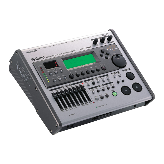
Roland V-DRUMS TD-20 Owner's Manual
Percussion sound module
Hide thumbs
Also See for V-DRUMS TD-20:
- Manual (76 pages) ,
- Cautions on using (1 page) ,
- Supplementary manual (1 page)
Table of Contents
Advertisement
Quick Links
Owner's Manual
We'd like to take a moment to thank you for purchasing the Roland Percussion Sound Module TD-20.
201b
Before using this unit, carefully read the sections entitled: "IMPORTANT SAFETY
INSTRUCTIONS" (p. 2), "USING THE UNIT SAFELY" (p. 3), and "IMPORTANT NOTES"
(p. 5). These sections provide important information concerning the proper operation
of the unit. Additionally, in order to feel assured that you have gained a good grasp
of every feature provided by your new unit, Owner's manual should be read in its
entirety. The manual should be saved and kept on hand as a convenient reference.
234
* CompactFlash and
are trademarks of SanDisk Corporation and licensed by Compact-
Flash association.
235
* Roland Corporation is an authorized licensee of the CompactFlash™ and CF logo (
trademarks.
236
* Fugue © 2004 Kyoto Software Research, Inc. All rights reserved.
202
Copyright © 2004 ROLAND CORPORATION
All rights reserved. No part of this publication may be reproduced in any form without the
written permission of ROLAND CORPORATION.
)
Advertisement
Table of Contents

Related Manuals for Roland V-DRUMS TD-20


Summary of Contents for Roland V-DRUMS TD-20
- Page 1 Owner’s Manual We’d like to take a moment to thank you for purchasing the Roland Percussion Sound Module TD-20. 201b Before using this unit, carefully read the sections entitled: “IMPORTANT SAFETY INSTRUCTIONS” (p. 2), “USING THE UNIT SAFELY” (p. 3), and “IMPORTANT NOTES”...
-
Page 2: Important Safety Instructions
CAUTION RISK OF ELECTRIC SHOCK DO NOT OPEN ATTENTION : RISQUE DE CHOC ELECTRIQUE NE PAS OUVRIR CAUTION: TO REDUCE THE RISK OF ELECTRIC SHOCK, DO NOT REMOVE COVER (OR BACK). NO USER-SERVICEABLE PARTS INSIDE. REFER SERVICING TO QUALIFIED SERVICE PERSONNEL. INSTRUCTIONS PERTAINING TO A RISK OF FIRE, ELECTRIC SHOCK, OR INJURY TO PERSONS. -
Page 3: Using The Unit Safely
Do not attempt to repair the unit, or replace parts within it (except when this manual provides specific instructions directing you to do so). Refer all servicing to your retailer, the nearest Roland Service Center, or an authorized Roland distributor, as listed on the “Information” page. - Page 4 • Immediately turn the power off, remove the power cord from the outlet, and request servicing by your retailer, the nearest Roland Service Center, or an authorized Roland distributor, as listed on the “Information” page when: • The power-supply cord, or the plug has been damaged;...
-
Page 5: Important Notes
However, in certain cases (such as when circuitry related to memory itself is out of order), we regret that it may not be possible to restore the data, and Roland assumes no liability concerning such loss of data. Memory Backup 501b •... - Page 6 (including padding) that it came in, if possible. Otherwise, you will need to use equivalent packaging materials. • Use a cable from Roland to make the connection. If using some other make of connection cable, please note the following precautions.
-
Page 7: Table Of Contents
Contents USING THE UNIT SAFELY ...3 IMPORTANT NOTES...5 Features ...11 Panel Descriptions ...13 Top Panel... 13 Rear Panel ... 15 Front Panel ... 16 Setting Up the Kit ...17 Mounting the TD-20 on the Stand ... 17 Connecting the Pads and Pedals... 18 Connecting Headphones, Audio Equipment, Amps, or Other Gear ... - Page 8 Contents Adjusting the Volume [F1 (VOLUME)]... 29 Assigning a Tempo for Each Kit [F2 (TEMPO)] ... 29 Playing Brushes [F3 (BRUSH)] ... 29 Output Level Monitor [F5 (MONITOR)]... 29 Naming a Drum Kit [F3 (NAME)]... 30 Playing Cross Stick [F5 (XSTICK)]... 30 Chapter 2.
- Page 9 Double Triggering Prevention (Mask Time)... 49 Rim/Edge Dynamic Response (Rim Gain)... 49 Rim Shots Response (Rim Shot Adjust)... 49 Cross Stick Threshold (XStick Thrshld)... 49 Playing Bow, Bell, and Edge (3-Way Triggering) ... 50 Naming a Trigger Bank [F5 (Name)] ... 50 Chapter 6.
- Page 10 Contents Chapter 10. Settings for the Entire TD-20 [SETUP] ...74 MIDI Settings and Operations [F1 (MIDI)] ... 74 Setting the MIDI Channels for Each Part [F1 (MIDI CH)]... 74 MIDI Settings for the Entire TD-20 [F2 (GLOBAL)] ... 74 MIDI Messages for Detailed Performance Expressions [F3 (CTRL)]... 76 Switching Drum Kits via MIDI (Program Change) [F4 (PROG)] ...
-
Page 11: Features
15 trigger inputs let you use lots of pads, leaving room for advanced Pad Switch applications. (p. 80) * COSM (Composite Object Sound Modeling) is a Roland technology combining multiple sound modeling processes to create new sounds hots. - Page 12 V-LINK function V-LINK ( ) is functionality promoted by Roland that allows linked performance of music and visual material. By using V-LINK-compatible video equipment, visual effects can be easily linked to, and made part of the expressive elements of a performance. By using the TD-20 and Edirol DV-7PR together, connected pads can be used to switch the Edirol DV-7PR’s images (clips/palettes) (p.
-
Page 13: Panel Descriptions
Panel Descriptions Top Panel fig.top 1. Trigger Level Indicator This lights up and moves each time a trigger signal is received from a pad. It monitors the pad connection and is helpful when customizing trigger parameters. 2. LED Display Displays the Kit number (currently selected drum kit). 3. - Page 14 Panel Descriptions 7. CARD Button For access to (Compact Flash) memory card functions such as saving/loading data etc. (p. 70) 8. SETUP Button For access to functions that affect the TD-20 globally, such as MIDI parameters etc. (p. 74) 9. TRIGGER Button For access to trigger parameters (p.
-
Page 15: Rear Panel
Rear Panel fig.rear_50 1. POWER Switch This switch turns the power on/off. 2. AC Inlet Connect the included AC power cable to this inlet. * For details on the power consumption, refer to p. 103. The unit should be connected to a power source only of the type marked on the bottom of the unit. -
Page 16: Front Panel
Panel Descriptions Front Panel fig.front 1. PHONES Jack A pair of stereo headphones can be connected to this jack. Connecting the headphones will not mute the output from the MASTER OUT jacks (p. 19). 2. CompactFlash Card Slot Accepts a CompactFlash memory card (optional). Each memory card can store all settings of the TD-20, such as drum kits and sequencer performance data, etc. -
Page 17: Setting Up The Kit
This unit should be used only with a stand that is recommended by Roland. When using the unit with a stand recommended by Roland, the rack or stand must be carefully placed so it is level and sure to remain stable. If not using a rack or stand, you still need to make sure that any location you choose for placing the unit provides a level surface that will properly support the unit, and keep it from wobbling. -
Page 18: Connecting The Pads And Pedals
Setting Up the Kit Connecting the Pads and Pedals Using the provided cables, connect the pads, cymbals, hi-hat, and kick trigger. * When mounting a TD-20 on an MDS-20 drum stand, use the built-in connection cables. Set Up Example fig.Kit.e 7 / HI-HAT HH CTRL TD-20... -
Page 19: Connecting Headphones, Audio Equipment, Amps, Or Other Gear
* When connection cables with resistors are used, the volume level of equipment connected to the MIX IN jack may be low. If this happens, use connection cables that do not contain resistors, such as those from the Roland PCS series. Setting Up the Kit Front Panel... -
Page 20: Turning On/Off The Power
Setting Up the Kit Turning On/Off the Power * Once the connections have been completed (p. 18, p. 19), turn on power to your various devices in the order specified. By turning on devices in the wrong order, you risk causing malfunction and/or damage to speakers and other devices. -
Page 21: Connecting The Hi-Hat (Vh-12) And Setting The "Vh Offset
Connecting the Hi-Hat (VH-12) and Setting the “VH Offset” Connecting the Hi-Hat TRIGGER OUTPUT jack TRIGGER INPUT HI-HAT jack Adjusting the Offset When using the VH-12, the “VH Offset” needs to be set up. 1. Loosen the clutch of the top hi-hat and let it sit on the bottom hi-hat. -
Page 22: Listening To The Demo Song
Listening to the Demo Song The internal demo song features the TD-20’s expressive capabilities and top quality sounds. The drums on this song were recorded from the TD-20 system to a sequencer in real time. 1. Press [CHAIN] and [TOOLS] simultaneously. -
Page 23: Button Operation And Displays
Button Operation and Displays Operations common to all aspects TD-20 operations. Saving Your Settings Every time you change a value during the editing process, it’s automatically stored in the TD-20’s memory. There’s no “write/save” process. (except when using a memory card) Buttons, Sliders, Dial and Knobs References for top panel buttons, sliders, dial and knobs will... -
Page 24: Group Faders
Button Operation and Displays Group Faders fig.00-009 Use [GROUP FADERS] sliders to adjust the volume. If you press the [FADER] button, the function of the faders will change as is explained in the chart below. An LED will light up at the upper and lower right of the faders to indicate which set of sounds is active. -
Page 25: How To Play Patterns
How to Play Patterns fig.06-003_70 Pressing [PATTERN]. The basic screen for the sequencer appears. Press [+/-] or turn [VALUE] in this screen to choose a pattern. Or press [F1 (LIST)] to choose from the pattern list. fig.06-001 Press [PLAY] to start playback of the pattern. Press [STOP] to stop playback. -
Page 26: Playing Methods
Playing Methods Pad (PD-125/105) fig.Play-Head.e Head Shot Hit only the head of the pad. With certain snare sounds, playing position will change the nuance of the sound. fig.Play-Rim.e Rim Shot Strike the head and the rim of the pad simultaneously. fig.Play-Cross.e Cross Stick Only strike the rim of the pad. -
Page 27: Cymbal (Cy-15R/14C)
With certain ride sounds, playing position will change the nuance of the sound. * Only TRIGGER INPUT 10 RIDE corresponds to the positional sensing. About the instruments corresponding to each playing method, refer to p. 95. Playing Methods Roland logo... -
Page 28: Chapter 1. Drum Kit Settings [Kit]
Chapter 1. Drum Kit Settings [KIT] Choosing a Drum Kit 1. Press [KIT]. [KIT] lights, and the “DRUM KIT” screen appears. fig.01-001*_70 2. Use [+/-] or [VALUE] to select drum kits. Foot switches or pads can be programmed to make selections (p. -
Page 29: Kit Parameters [F2 (Func)]
Kit Parameters [F2 (FUNC)] 1. Press [KIT] - [F2 (FUNC)]. 2. Press [F1]–[F3] and [CURSOR (up/down)] to select the parameter. 3. Use [+/-] or [VALUE] to make settings. Adjusting the Volume [F1 (VOLUME)] fig.01-003_70 Parameter Value Description Kit Volume 0–127 Volume of the entire drum Pedal HH Volume 0–127... -
Page 30: Naming A Drum Kit [F3 (Name)]
Chapter 1. Drum Kit Settings [KIT] Naming a Drum Kit [F3 (NAME)] Each kit’s name can use up to 12 characters. fig.01-005_70 1. Press [KIT] - [F3 (NAME)]. The “DRUM KIT NAME” screen appears. 2. Press [CURSOR (left/right)] to move the cursor to the character to be changed. -
Page 31: Chapter 2. Drum Instrument Settings [Inst]
Chapter 2. Drum Instrument Settings [INST] Here’s how to select and edit sounds, such as the snare drum and kick drum. Choosing a Pad to Edit There are two basic ways to select the sound you want to edit. Choose by Hitting a Pad 1. -
Page 32: Selecting An Instrument From The List [F1 (List)]
Chapter 2. Drum Instrument Settings [INST] Selecting an Instrument from the List [F1 (LIST)] Here you can select from the list of all available instruments. fig.02-003_70 1. Press [INST] - [F1 (LIST)]. The “INST LIST” screen appears. 2. Strike a pad. The settings screen for the struck pad appears. - Page 33 KICK fig.02-KICK_70 Parameter Value [F1 (SHELL)] Shell Depth NORMAL, DEEP1–2 Beater Type FELT, WOOD, PLASTIC [F2 (HEAD)] Head Type CLEAR, COATED, PINSTRIPE Head Tuning -480–+480 [F3 (MUFFLE)] Muffling OFF, TAPE1–2, BLANKET, WEIGHT Snare Buzz OFF, 1–8 [F4 (MIC)] Mic Position OUTSIDE2–1, STANDARD, INSIDE1–2 SNARE...
- Page 34 Chapter 2. Drum Instrument Settings [INST] CRASH/SPLASH/CHINA/RIDE fig.02-CYM_70 Parameter Value [F1 (SIZE)] Size 1”–40” [F2 (SIZZLE)] Sizzle Type OFF, RIVET, CHAIN [F3 (SUSTAIN)] Sustain -31–+31 [F4 (MIC)] Mic Position OUTSIDE2–1, STANDARD, INSIDE1–2 Other Instruments fig.02-005_70 Parameter Value Pitch -480–+480 Decay Time -31–+31 You can edit the instruments of the head and rim simultaneously.
-
Page 35: Using Pads/Pedal As Controllers [F3 (Control)]
Using Pads/Pedal as Controllers [F3 (CONTROL)] 1. Press [INST] - [F3 (CONTROL)]. 2. Strike a pad. The settings screen for the struck pad appears. You can select by using [TRIG SELECT]. 3. Press [F1]–[F5] and [CURSOR (up/down)] to select the parameter. 4. -
Page 36: Midi Settings For Each Pad [F3 (Midi)]
Chapter 2. Drum Instrument Settings [INST] MIDI Settings for Each Pad [F3 (MIDI)] Tx Channel: CH1–CH16, GLOBAL MIDI transmit channel for each pad. GLOBAL: Transmits on the same channel as the drum kit part (p. 74). Note No.: 0 (C -)–127 (G 9), OFF OFF: Note messages are not transmitted. -
Page 37: Chapter 3. Mixer Settings
Chapter 3. Mixer Settings Mixer Parameters [MIXER] Here you can adjust the volume, pan, etc. fig.03-001_70 1. Press [MIXER]. [MIXER] lights. 2. Use [F1]–[F5] or [CURSOR (up/down)] to select the parameter. 3. Use TRIG SELECT [1], [15], [RIM], or [CURSOR (left/right)] to select the instrument you wish to set. -
Page 38: Chapter 4. Effect Settings
Chapter 4. Effect Settings Effects On and Off Switches [EFFECTS SWITCH] These switches allow you to turn all individual effects and master effects on/off within each drum kit. fig.04-001_70 1. Press [EFFECTS SWITCH]. [EFFECTS SWITCH] lights, and the “EFFECTS SWITCH” screen appears. -
Page 39: Compressor (Comp)
Compressor (COMP) A compressor adjusts the envelope (changes in the volume over time) and changes the character of the sound in response to playing dynamics. fig.04-003_70 Parameter Value Attack EMPHASIS, CRUSH Type COMP SOFT 1–2, COMP MED 1–3, COMP HARD 1–2, LIMITER 1–2, EXPANDER 1–3 Time... -
Page 40: Ambience [Ambience]
Chapter 4. Effect Settings Ambience [AMBIENCE] You can choose the type of room where the drums are to be played and modify the sound. fig.04-005_70 1. Press [AMBIENCE]. [AMBIENCE] lights. 2. Press [F2]–[F4] or [CURSOR] to select the parameter. 3. Use [+/-] or [VALUE] to adjust the setting. -
Page 41: Multi-Effects Parameters
Multi-Effects Parameters REVERB Adds reverberation to the sound, simulating an acoustic space. Parameter Value Description Room Type 1–5 Type of reverb PreDly 0–100.0 (ms) Time until the reverb is heard Time 0–127 Duration of reverbera- tion HiDamp 4.0k–12.5k (Hz), Frequency above which THRU the reverb is reduced in level... - Page 42 Chapter 4. Effect Settings FLANGER Produces a metallic resonance that rises and falls somewhat like a jet airplane taking off or landing. Parameter Value Description Delay 0–15.0 (ms) Tone of the flanger LFO Rate 1–128 Frequency of modulation Depth 0–127 Depth of modulation Feedback -98–98 (%)
-
Page 43: Master Effects [Master Comp/Eq]
LO-FI Intentionally degrades the sound quality for creative purposes. Parameter Value Description Fs Rate OFF, 1/2–1/32 Sample rate OFF, 15–1 Number of bits in data BPF Cutoff 0–100 Cutoff frequency of the BPF (Band Pass Filter) BPF Mix 0–127 Amount of mixing the sound that goes through the BPF RING MOD... -
Page 44: Chapter 5. Trigger Settings [Trigger]
CY-12R/C CY14C CY-14C CY-8 CY-6 CY12H CY-12H VH12 VH-12 KICK When using a non-Roland kick trigger PAD1 When using a non-Roland pad PAD2 RT7K RT-7K RT5S RT-5S RT3T RT-3T * When you select the trigger type, the trigger parameters (except the crosstalk cancel parameters) are automatically set to the most efficient values for each pad. -
Page 45: Setting The Pad Sensitivity [F2 (Basic)]
Setting the Pad Sensitivity [F2 (BASIC)] When you are using pads made by other manufacturers, try adjusting the following parameters. 1. Press [TRIGGER] - [F2 (BASIC)]. [TRIGGER] lights, and the “TRIGGER BASIC” screen will appear. fig.05-TrigBasic_70 2. Use [CURSOR (up/down)] to select the parameter. -
Page 46: Hi-Hat Settings [F3 (Hi-Hat)]
Chapter 5. Trigger Settings [TRIGGER] Curve: LOG1, LOG2 Compared to LINEAR, a soft playing produces a greater change. fig.VeloC-LOG.e Volume Volume LOG1 LOG2 Curve: SPLINE Extreme changes are made in response to playing dynamics. fig.VeloC-SPLINE.e Volume Striking Force SPLINE Curve: LOUD1, LOUD2 Very little dynamic response, making it easy to maintain strong volume levels. -
Page 47: Eliminate Crosstalk Between Pads [F4 (Xtalk)]
Eliminate Crosstalk Between Pads [F4 (XTALK)] When two pads are mounted on the same stand, hitting one pad may trigger the sound from another pad unintentionally. (This is called crosstalk.) Eliminate this by adjusting Xtalk Cancel on the pad that is sounding inadvertently. In some cases, you can prevent crosstalk between two pads by increasing the distance between them. -
Page 48: Advanced Trigger Parameters [F5 (Advance)]
* Although setting this to a high value prevents retriggering, it then becomes easy for sounds to be omitted when the drums played fast (roll etc.). Set this to the lowest value possible while... -
Page 49: Double Triggering Prevention (Mask Time)
When playing a kick trigger the beater can bounce back and hit the head a second time immediately after the intended note—with acoustic drums sometimes the beater stays against the head—this causes a single hit to “double trigger” (two sounds instead of one). The Mask Time setting helps to prevent this. -
Page 50: Playing Bow, Bell, And Edge (3-Way Triggering)
Chapter 5. Trigger Settings [TRIGGER] Playing Bow, Bell, and Edge (3-Way Triggering) When using the CY-15R or CY-12R/C for the RIDE, you can three way triggering (bow, bell, and edge shot) performance are possible. 3Way Trigger: OFF, ON Connect as shown below, set 3Way Trigger to “ON.” fig.05-Ride.e Ride CY-15R or CY-12R/C... -
Page 51: Chapter 6. Sequencer (Playback)
CD-ROM or equivalent means. The sound recordings contained in this product are the original works of Roland Corporation. Roland is not responsible for the use of the sound recordings contained in this product, and assumes no liability for any infringement of any copyright of any third party arising out of use of the sounds, phrases and patterns in this product. -
Page 52: Choosing A Pattern [Pattern]
Chapter 6. Sequencer (Playback) Choosing a Pattern [PATTERN] fig.06-003_70 1. Press [PATTERN]. [PATTERN] lights, and the “PATTERN” screen appears. 2. Use [+/-] or [VALUE] to select the pattern. * If you press [F5 (NEW)], an empty pattern with the lowest number is called up. -
Page 53: Tempo Adjustment
Tempo Adjustment 1. Press [TEMPO]. 2. [TEMPO] lights, and the “TEMPO” screen appears. fig.06-Tempo1_70 3. Use [+/-] or [VALUE] to select the tempo. 4. Press [EXIT] to return to the “DRUM KIT” screen. Setting the Tempo by Hitting a Pad (Tap Tempo) You can set the tempo by hitting a pad or [PREVIEW] two or more times at quarter-note intervals of the desired tempo. -
Page 54: Part Settings [F2 (Part)]
Chapter 6. Sequencer (Playback) Part Settings [F2 (PART)] PATTERN PART screen (Only for User Pattern) fig.06-Part_70 Muting a Specific Part [F1 (MUTE)] You can mute specific parts in user patterns. 1. Press [PATTERN] - [F2 (PART)]. The “PATTERN PART” screen appears. 2. -
Page 55: Master Tuning
Instrument Numbers/Instrument Names You can change the tone by changing the instrument number. Selecting different variations within each instrument number changes the instrument name, with a different tone being selected. Instrument numbers correspond to the program numbers (1-128). Variation Tones These are slightly varied tone types found in an instrument number. - Page 56 Chapter 6. Sequencer (Playback) Selecting a Percussion Instrument from the List [F1 (LIST)] Here you can select from the list of all available instruments. 1. Press [CURSOR (up/down)] to select the note number you wish to set. 2. Press [F1 (LIST)]. The “PERCUSSION SET INST LIST”...
-
Page 57: Volume/Pan Settings For Each Part [F4 (Mixer)]
Volume/Pan Settings for Each Part [F4 (MIXER)] * Drum part cannot be set here. Set in the MIXER settings (p. 37). * To adjust volume/pan settings for each instrument of the percussion part, refer to p. 55. 1. Press [PATTERN] - [F2 (PART)]. The “PATTERN PART”... -
Page 58: Pattern Settings [F3 (Func)]
Chapter 6. Sequencer (Playback) Pattern Settings [F3 (FUNC)] Set various settings for the user patterns. Time Signature/Number of Measures/Tempo Settings [F1 (SETUP)] 1. Press [PATTERN]. The “PATTERN PART” screen appears. 2. Press [F3 (FUNC)] - [F1 (SETUP)]. The “PATTERN SETUP” screen appears. fig.06-PtnSetup_70 3. -
Page 59: Naming A Pattern [F5 (Name)]
Supplementary function for TAP and V-LINK Tap Reset Time: OFF, 0.2–4.0 (sec) This function automatically returns the pattern to the beginning if the set time interval elapses without the pad being hit again. This is the time interval that resets the pattern being used. -
Page 60: Setting The Click
Chapter 6. Sequencer (Playback) Setting the Click 1. Press [TEMPO] - [F1 (CLICK)]. The “CLICK SETTINGS” screen appears. fig.06-Click5_70 2. Press [CURSOR] to select the parameter. 3. Use [+/-] or [VALUE] to make settings. Parameter Value [F1 (INST)] Inst Refer to right col- umn. -
Page 61: Chapter 7. Sequencer (Recording/Editing)
Chapter 7. Sequencer (Recording/Editing) Recording a Pattern [REC] What is played on the pads or on an external MIDI keyboard can be recorded (Realtime Recording). Your performance will be recorded exactly as you play it, including hi-hat control pedal movements and Positional Sensing. - Page 62 Chapter 7. Sequencer (Recording/Editing) (2) Set the Time Signature, the Number of Measures, and the Tempo 1. In the “PATTERN” screen, press [F3 (FUNC)] - [F1 (SETUP)]. The “PATTERN SETUP” screen appears. fig.07-Rec2-1_70 2. Press [CURSOR] to select the parameter. 3.
-
Page 63: Checking The Tones And Phrases During Recording (Rehearsal)
(5) Set the Recording Method 1. In the “PATTERN” screen, press [REC]. [PLAY] flashes, and [REC] lights. The “PATTERN REC STANDBY” screen appears, and the click sound begins to play. fig.07-Rec5-1_70 2. Press [CURSOR (up/down)] to select the parameter. 3. Use [+/-] or [VALUE] to make settings. Parameter Value Description... -
Page 64: Editing A Pattern [F4 (Edit)]
Chapter 7. Sequencer (Recording/Editing) Editing a Pattern [F4 (EDIT)] You can edit user patterns. PATTERN EDIT screen (Preset Pattern) fig.07-PrstEdit_70 PATTERN EDIT screen (User Pattern) fig.07-UserEdit_70 Copying a Pattern [F1 (COPY)] Copy the pattern as is to the User patterns. fig.07-Cpy1 You can copy selected measures of a part or pattern. -
Page 65: Connecting Two Patterns [F2 (Append)]
Connecting Two Patterns [F2 (APPEND)] This connects two patterns to create one pattern. The pattern specified as “Dst” will be first, and the pattern specified as “Src” will be connected to it. The new pattern will be created in “Dst.” fig.07-Apd1 1. -
Page 66: Deleting A Pattern [F4 (Delete)]
Chapter 7. Sequencer (Recording/Editing) Pattern Part Measure Pattern to be Part to be Measures to be erased erased erased (First Measure–Last Measure) 6. Press [F5 (ERASE)]. The confirmation screen appears. fig.07-Ers5_70 7. Press [F5 (EXECUTE)]. * To cancel, press [F1 (CANCEL)]. Deleting a Pattern [F4 (DELETE)] This deletes the pattern performance, beat, measure length, part, and all other settings, creating a empty pattern. -
Page 67: Saving Patterns To A Memory Card [F5 (Card)]
Saving Patterns to a Memory Card [F5 (CARD)] You can use an optional CompactFlash memory card to save pattern data. PATTER CARD screen fig.07-PtnCard_70 930 (Modified) * Never remove a CompactFlash card while the CompactFlash indicator on the TD-20’s top panel is lit. Doing so may corrupt the unit’s data or the data on the CompactFlash card. - Page 68 Chapter 7. Sequencer (Recording/Editing) Loading a Pattern from a Memory Card [F2 (LOAD)] Patterns saved on a memory card can be loaded into the TD- 1. Insert a CompactFlash card into the CompactFlash card slot on the TD-20’s front panel. 2.
-
Page 69: Chapter 8. Copy Function [Copy]
Chapter 8. Copy Function [COPY] You can copy drum kits, instruments, etc. to the destination of your choice. Copying will overwrite the data that was in the new destination. So take caution when performing this operation. 1. Press [COPY]. [COPY] lights, and the “COPY” screen appears. If a CompactFlash card is inserted into the CompactFlash card slot, the CompactFlash indicator also lights (p. -
Page 70: Chapter 9. Using A Compactflash Memory Card [Card]
Chapter 9. Using a CompactFlash Memory Card [CARD] You can use an optional CompactFlash memory card to save TD-20 settings and sequencer data. CARD MENU screen fig.09-CardMenu_70 930 (Modified) * Never remove a CompactFlash card while the CompactFlash indicator on the TD-20’s top panel is lit. Doing so may corrupt the unit’s data or the data on the CompactFlash card. -
Page 71: Naming A Backup [F4 (Name)]
Naming a Backup [F4 (NAME)] Each backup area can be given a name of up to 12 characters. 1. In the “CARD SAVE” confirmation screen, press [F4 (NAME)]. The “CARD SAVE NAME” screen appears. fig.09-CardName_70 2. Press [CURSOR (left/right)] to move the cursor to the character to be changed. -
Page 72: Deleting Data From A Memory Card [F3 (Delete)]
Chapter 9. Using a CompactFlash Memory Card [CARD] Deleting Data from a Memory Card [F3 (DELETE)] You can delete the unneeded data from a memory card. 1. Insert the CompactFlash card into the CompactFlash card slot on the TD-20’s front panel. -
Page 73: Checking The State Of A Memory Card [F5 (Info)]
Checking the State of a Memory Card [F5 (INFO)] 1. Insert a CompactFlash card into the CompactFlash card slot on the TD-20’s front panel. 2. PRESS [CARD]. [CARD] AND the CompactFlash indicator light, and the “CARD MENU” screen appears. 3. Press [F5 (INFO)]. The “CARD INFORMATION”... -
Page 74: Chapter 10. Settings For The Entire Td-20 [Setup]
V-LINK Device ID 1–32, 128 Soft Thru This section explains how you can use the Roland SPD-20 (a MIDI controller) together with the TD-20’s pads to play internal sounds and an external sound module. When Soft Thru is set to “ON,” the messages received at MIDI IN will also be transmitted from the MIDI OUT/THRU connector. -
Page 75: Local Control
Local Control This is required when you want to trigger sounds in an external sound module and/or record your performance on an external MIDI sequencer, and NOT use the TD-20’s internal sounds. If that is your need, then turn Local Control to “OFF.” The trigger signals from the pads go directly to the MIDI OUT/THRU connector. -
Page 76: Midi Messages For Detailed Performance Expressions [F3 (Ctrl)]
Chapter 10. Settings for the Entire TD-20 [SETUP] MIDI Messages for Detailed Performance Expressions [F3 (CTRL)] 1. Press [SETUP]. [SETUP] lights. 2. Press [F1 (MIDI)] - [F3 (CTRL)]. The “MIDI CONTROL” screen appears. fig.10-MidiCtrl_70 3. Press [CURSOR (up/down)] to select the parameter. -
Page 77: Saving Data To An External Midi Device (Bulk Dump) [F5 (Bulk)]
Saving Data to an external MIDI Device (Bulk Dump) [F5 (BULK)] Saving Data To save data, use the external sequencer as you would when recording musical data, and perform the following steps on the TD-20 as shown in the following diagram. 1. -
Page 78: Selecting Output Destinations [F2 (Output)]
Chapter 10. Settings for the Entire TD-20 [SETUP] Selecting Output Destinations [F2 (OUTPUT)] Here you can select the output destination for each TRIGGER INPUTs, sequencer parts, and the sound input from the MIX IN jack. Output Destination for the Drum Instruments 1. -
Page 79: Setting The Switches [F3 (Control)]
Setting the Switches [F3 (CONTROL)] Using Foot Switches [F1 (FOOT SW)] Two foot switches (BOSS FS-5U, optional) can be used with an optional cable (PCS-31) to switch drum kits and play back patterns. fig.FootSw.e FS-5U Foot Switch FS-5U x 2 (PCS-31) o (red plug) DP-2 –... -
Page 80: Using Pads As Switches [F2 (Pad Sw)]
Chapter 10. Settings for the Entire TD-20 [SETUP] Using Pads as Switches [F2 (PAD SW)] Pads connected to TRIGGER INPUT 15 (AUX4) and/or 14 (AUX3) can be set to switch drum kits and play back patterns. 1. Connect the pad(s) to the TRIGGER INPUT 15 (AUX 4) and/or 14 (AUX3). -
Page 81: Master Effect Mode [F2 (Comp/Eq)]
Master Effect Mode [F2 (COMP/EQ)] You can specify which is used for the master effect (p. 43), individual settings for each drum kit or common settings to all kits. 1. Press [SETUP]. [SETUP] lights. 2. Press [F4 (OPTION)] - [F2 (COMP/EQ)]. The “MASTER COMP/EQ MODE”... -
Page 82: Chapter 11. Drum Kit Chain [Chain]
Chapter 11. Drum Kit Chain [CHAIN] Drum Kit Chain allows you to step through the drum kits of your choice and in the order you want. The TD-20 lets you create and store 16 different chains of up to 32 steps each. fig.11-001e 32 steps Chain 1... -
Page 83: Naming A Drum Kit Chain [F5 (Name)]
Naming a Drum Kit Chain [F5 (NAME)] Each chain’s name can use up to 12 characters. fig.11-ChainName_70 1. Select the drum kit chain you want to name in the “DRUM KIT CHAIN” screen. 2. Press [F1 (C EDIT)] - [F5 (NAME)]. The “CHAIN NAME”... -
Page 84: Chapter 12. Other Functions [Tools]
What is V-LINK? V-LINK ( ) is functionality promoted by Roland that allows linked performance of music and visual material. By using V-LINK-compatible video equipment, visual effects can be easily linked to, and made part of the expressive elements of a performance. -
Page 85: Using V-Link
Using V-LINK Turning V-LINK On/Off 1. Press [TOOLS]. [TOOLS] lights, and the “TOOLS” screen appears. fig.12-Tools_70 2. Press [F5 (V-LINK)] to turn the V-LINK function ON and OFF. fig.12-VLinkOn1_70 * Before turning V-LINK on, turn the Edirol DV-7PR’s power 3. Press [KIT] or [EXIT] to display the “DRUM KIT” screen. -
Page 86: About Expansion Board
The bottom panel of the TD-20 has a slot that allows expansion boards to be installed. Install only the specified circuit board (SOUND & SYSTEM EXPANSION BOARD for TD-20). * Sound expansion boards for the Roland JV/XP/XV/Fantom series cannot be used. Cautions When Installing a Expansion Board •... - Page 87 4. While positioning the holes on the board over the board holders, carefully insert the connector on the board into the socket on the TD-20. Make sure the connector is securely connected, and that all three board holders project through the holes. 5.
-
Page 88: À Propos Des Carte D'extension
N’installez que la ou les carte de circuits imprimés spécifiée. (SOUND & SYSTEM EXPANSION BOARD pour TD-20) * Les cartes d’extension de son pour les séries JV/XP/XV/Fantom de Roland ne peuvent être utilisées. Précautions à prendre lors de l’installation d’une carte d’extension... - Page 89 4. Pendant que vous alignez les trous de la carte au-dessus des supports, insérez délicatement le connecteur sur la carte dans la prise du TD- 20. Assurez-vous que le connecteur est raccordé correctement et que les trois supports s’emboîtent bien dans les trous. 5.
-
Page 90: Messages And Error Messages
The checksum value of a system exclusive Checksum Error! message was incorrect. Action Contact your dealer or a nearby Roland service center to have the battery replaced. Contact your dealer or a nearby Roland service center to have the battery replaced. Follow the messages appearing on the screen to carry out Factory Reset (p. - Page 91 Message Meaning BULK DUMP The receive address of a system exclusive Receive Address Error! message was incorrect. BULK DUMP A MIDI message was received incorrectly. Receive Data Error! BULK DUMP The interval in receiving system exclusive Receive Time Out! messages were too long. Messages Message Meaning...
-
Page 92: Drum Instrument List
Drum Instrument List Name Remark KICK 22”Birch 22”Solid 22”StdMple K 22”Maple 24”Carbon 22”CbnMple K 22”GT 22”TitanHp K 22”Mahogny K 20”Lite 22”RoseWd 22”Oak Recording1 K Recording2 K Universal BigOpen JazzCombo1 K JazzCombo2 K Cannon Roto Booth Ballad Swing Heavy Fusion Latin Meat Pillow DryMed... - Page 93 Name Remark 12”Birch T1 12”Birch T1R 13”Birch T2 13”Birch T2R 16”Birch T3 16”Birch T3R 18”Birch T4 18”Birch T4R 12”GT 12”GT 13”GT 13”GT 16”GT 16”GT 18”GT 18”GT 10”Univ 10”Univ 12”Univ 12”Univ 14”Univ 14”Univ 16”Univ 16”Univ 12”Clasc T1 12”Clasc T1R 13”Clasc T2 13”Clasc T2R 16”Clasc T3 16”Clasc T3R...
- Page 94 Drum Instrument List Name Remark SPLASH 6”SplazhSpBw 6”SplazhSpEg 8”Thin SpBw 8”Thin SpEg 8”Bell SpBw 8”Bell SpEg 8”Open SpBw 8”Open SpEg 10”Med SpBw 10”Med SpEg CHINA 12”PgyBack 12”PgyBackEg 16”Swish 16”Swish 18”CB Low 18”CB Low Eg 20”U-China China PgBack Crash PgBack RIDE 18”PRideRd 18”PRideRdBl 18”PRideRdEg...
- Page 95 When you purchase the TD-20 percussion sound module from an authorized Roland dealer, the included sounds are licensed, not sold, to you by Roland Corporation, for commercial use in music production, public performance, broadcast, etc. You may use any of the included...
-
Page 96: Note Number (Factory Settings)
Note Number (Factory Settings) Percussion Set 1. Latin Toys Note No. Bass Gliss GuitarScrtch WahGt1 Down WahGt1 Up WahGt2 Down WahGt2 Up CR78Guiro CR78Tamb TR808Clap TR808Cowbell TR808Maracas TR909Clap Hi-Q R8Slap Scratch2 Scratch3 Sticks Click MetroClick MetroBell Clap VibraSlap SquareBlock Beep Crotale SquareBlock 6"SplazhSpEg... - Page 97 Note No. Bongo Hi Bongo Lo Conga Hi Conga HiSlap Conga Lo Timbale Hi Timbale Lo Agogo Hi Agogo Lo Cabasa Maracas WhistleShort Whistle Guiro Short Guiro Long Claves Block Hi Block Lo Cuica Hi Cuica Lo TriangleCls Triangle Shaker SleighBell BellTree Castanet...
-
Page 98: Backing Instrument List
Backing Instrument List CC0 Name VOICES PIANO PIANO 1 PIANO 1W PIANO 1D PIANO 2 PIANO 2W PIANO 3 PIANO 3W HONKY-TONK HONKY-TONK W E. PIANO E.PIANO 1 DETUNED EP 1 60’S E.PIANO FM+SA EP HARD RHODES E.PIANO 2 BRIGHT FM EP CLAVI HARPSICHORD COUPLED HPS. - Page 99 SITAR 2 BANJO SHAMISEN KOTO TAISHO KOTO KALIMBA BAGPIPE FIDDLE SHANAI PERCUSSIVE TINKLE BELL AGOGO STEEL DRUMS Backing Instrument List WOODBLOCK CASTANETS TAIKO CONCERT BD MELO. TOM 1 MELO. TOM 2 SYNTH DRUM 808 TOM ELEC PERC. REVERSE CYM. GUITAR BASS FX GT.FRETNOISE...
-
Page 100: Midi Implementation Chart
MIDI Implementation Chart PERCUSSION SOUND MODULE Model TD-20 Function... Basic Default Channel Changed Default Mode Messages Altered Note Number : True Voice Note On Velocity Note Off After Key’s Touch Channel’s Pitch Bend 0, 32 6, 38 Control Change 16–19 100, 101 Program Change... - Page 101 PERCUSSION SOUND MODULE MIDI Implementation Chart Model TD-20 Function... Basic Default 1–16, OFF Channel Changed 1–16, OFF Default Mode 3 Mode Messages Altered ************** Note 0–127 Number : True Voice ************** Note On O 9nH, v = 1–127 Velocity Note Off O 8nH, v = 64 After Key’s...
-
Page 102: Specifications
Specifications TD-20: Percussion Sound Module Sound Generator Variable Drum Modeling Maximum Polyphony 64 Voices Instruments Drum Instruments: 560 Backing Instruments: 262 Drum Kits Drum Kit Chains 16 chains (32 steps per chain) Instrument Parameters V-EDIT (KICK): Shell Depth, Beater Type, Head Type, Head Tuning, Muffling, Snare Buzz, Mic Position V-EDIT (SNARE): Shell Material, Shell Depth, Head Type, Head Tuning,... -
Page 103: Power Supply
It provides complete details concerning the way MIDI has been implemented on this unit. If you should require this publication (such as when you intend to carry out byte- level programming), please contact the nearest Roland Service Center or authorized Roland distributor. 962a... -
Page 104: Td-20 Block Diagram
Drums INST COMP/ Head INST COMP/EQ 1 KICK INST COMP/EQ Head INST COMP/EQ 2 SNARE INST COMP/EQ Head 3 TOM1 INST COMP/EQ INST COMP/EQ 6 TOM4 Head INST COMP/EQ 7 HI-HAT INST COMP/EQ Head INST COMP/EQ 8 CRASH1 INST COMP/EQ... - Page 105 SETUP MULTI MIXER /OUTPUT EFFECTS /PAN /MASTER MFX Send MFX Send MFX Send MFX Send MFX Send MFX Send MFX Send MFX Send MFX Send SETUP /OUTPUT MFX Send /DIRECT MFX Send MFX Send MFX Send MFX Send MFX Send MFX Send SETUP /OUTPUT...
-
Page 106: Index
Index Symbols +/- ... 14, 23 Numerics 3-WAY ... 48 Acoustic Drum Kit ... 32 Add Tambourine ... 33 ADVANCE ... 48 AMB SEND LEVEL ... 37 Amb Send Level ... 60 APPEND ... 65 Backing Instrument ... 98 Backing Part ... 57 BANK ... - Page 107 F RESET ... 81 Factory Reset ... 81 FADER ... 24, 37 FIXED ... 33 Fixed Hi-Hat ... 33 Foot Splash Sens ... 46 FOOT SW ... 79 FOOT SWITCH ... 15 Foot Switch ... 79 FORMAT ... 72 FUNC ... 29 Function Button ...
- Page 108 Index ONESHOT ... 58 Open Rim Shot ... 26 OPTION ... 80 Other Instruments ... 34 OUTPUT ... 78 Output ... 60 Output Destination ... 78 Output Level ... 29, 84 Pad ... 18, 21, 26 Pad Pattern ... 35 Pad Ptn Velocity ...
- Page 109 Index TAMB ... 33 TAP ... 58–59 Tap Ptn Mute Grp ... 35 Tap Reset Time ... 58–59 TEMPO ... 29 Tempo ... 25, 53, 58, 62 Tension ... 21 Threshold ... 45 Time ... 57 Time Signature ... 58, 60, 62 TIMESIG ...
-
Page 110: Preset Drum Kit List
*3: Parameters including volume etc. are set to standard values. Use this when creating a kit from scratch. Preset Pattern List No. Name T.S Len Tempo 1 Drums POP 2 Drums JAZZ 3 Drums BALLAD 12/8 4 Drums H.ROCK 5 Rockin’ Hard... - Page 111 Apparatus containing Lithium batteries ADVARSEL! Lithiumbatteri - Eksplosionsfare ved fejlagtig håndtering. Udskiftning må kun ske med batteri af samme fabrikat og type. Levér det brugte batteri tilbage til leverandøren. ADVARSEL Eksplosjonsfare ved feilaktig skifte av batteri. Benytt samme batteritype eller en tilsvarende type anbefalt av apparatfabrikanten.
- Page 112 Information When you need repair service, call your nearest Roland Service Center or authorized Roland distributor in your country as shown below. PHILIPPINES AFRICA AFRICA G.A. Yupangco & Co. Inc. 339 Gil J. Puyat Avenue EGYPT Makati, Metro Manila 1200,...
Need help?
Do you have a question about the V-DRUMS TD-20 and is the answer not in the manual?
Questions and answers