
Related Manuals for SMC Networks HRSF150-A 40 Series


Summary of Contents for SMC Networks HRSF150-A 40 Series
- Page 1 DOC1055019 Installation・Operation PRODUCT NAME Thermo Chiller MODEL / Series / Product Number HRSF150-A -40- HRSF150-W -40- HRSF200-A -40- HRSF200-W -40-...
- Page 2 DOC1055019 To the users Thank you for purchasing SMC’s Thermo chiller (hereinafter referred to as the “product”). For safety and long life of the product, be sure to read this operation manual (hereinafter referred to as the “manual”) and clearly understand the contents. ⚫...
-
Page 3: Table Of Contents
DOC1055019 Contents Contents Chapter 1 Safety Instructions ............1-1 Before Using the Product ..................1-1 Reading the Manual ....................1-2 Hazards ........................1-2 1.3.1 Level of hazards ........................1-2 1.3.2 Definition of “Serious injury” and “Minor injury” ..............1-3 1.3.3 Types of hazard labels ...................... - Page 4 DOC1055019 Contents 3.3.2 Electrical wiring ........................3-13 3.3.3 Preparation and wiring of power supply cable ..............3-15 3.3.4 Contact input/output communicatin wiring ................. 3-20 3.3.5 Wiring of run/stop signal input and remote signal input ............. 3-20 3.3.6 Wiring of external switch signal input ................3-23 3.3.7 Wiring of contact output signal ..................
- Page 5 DOC1055019 Contents 5.5.2 Checking with the check monitor menu ................5-9 Key-lock ......................... 5-13 5.6.1 Key-lock ..........................5-13 5.6.2 Key-lock setting / checking ....................5-14 Run Timer and Stop Timer Function ..............5-15 5.7.1 Run timer and stop timer function ..................5-15 5.7.2 Setting and checking of run timer and stop timer function ..........
- Page 6 DOC1055019 Contents 5.19.1 Alarm buzzer sound setting ....................5-46 5.19.2 Setting/checking of alarm buzzer sound ................5-46 5.20 Alarm Customizing Function ................5-47 5.20.1 Alarm customizing function ....................5-47 5.20.2 Setting and checking of the alarm customizing function ........... 5-51 5.20.3 Setting of temperature alarm monitoring method and alarm generation timing ....
- Page 7 DOC1055019 Contents 8.3.1 HRSF150/200-A-40- ...................... 8-17 8.3.2 HRSF150/200-W-40- ..................... 8-18 Cooling Capacity ....................8-19 8.4.1 HRSF150-A-40- ......................8-19 8.4.2 HRSF200-A-40- ......................8-19 8.4.3 HRSF150-W-40- ......................8-20 8.4.4 HRSF200-W-40- ......................8-20 Pump Capacity ...................... 8-21 8.5.1 HRSF150/200-A40- HRSF150/200-W-40- ..............8-21 8.5.2 Option T “High head pump”...
- Page 8 DOC1055019 Contents HRSF Series...
-
Page 9: Chapter 1 Safety Instructions
DOC1055019 Chapter 1 Safety Instructions Chapter 1 Safety Instructions Before using the product, be sure to read and understand all the important actions highlighted in this manual. 1.1 Before Using the Product ⚫ This "Safety" chapter describes the safety-related items that users should be aware of upon handling this system. -
Page 10: Reading The Manual
DOC1055019 Chapter 1 Safety Instructions 1.2 Reading the Manual This manual contains symbols to help identify important actions when installing, operating or maintaining the product. This sign indicates actions that must be followed. This sign indicates prohibited actions. 1.3 Hazards 1.3.1 Level of hazards The instructions given in this manual aim to assure the safe and correct operation of the product, and... -
Page 11: Definition Of "Serious Injury" And "Minor Injury
DOC1055019 Chapter 1 Safety Instructions Definition of “Serious injury” and “Minor injury” 1.3.2 ◼ “Serious injury” This term describes injuries that result in aftereffects including loss of eyesight, burns, electric shock, fracture, poisoning, etc. and requires long- term treatment or hospitalization. ◼... - Page 12 DOC1055019 Chapter 1 Safety Instructions ◼ Labels of Fire Hazard Fire Hazard This product uses a flammable refrigerant (R454C). Follow the contents of this fire warning label and safety precautions and handling instructions. ◼ Warning related to other general dangers This symbol stands for general danger.
-
Page 13: Locations Of Hazard Labels
DOC1055019 Chapter 1 Safety Instructions 1.3.4 Locations of Hazard Labels There are various warning labels on the product to show the potential hazards. For air-cooled type Fig. 1-1 Warning label position Fig. 1-2 Warning label position HRSF Series 1.3 Hazards... -
Page 14: Product Label
DOC1055019 Chapter 1 Safety Instructions 1.4 Product Label Information about the product, such as Serial No. and Model No. can be found on the product label. This information is needed when contacting an SMC sales distributor. Model number Serial number Kind and amount of refrigerant How to see the serial number C U 001 (JUL. -
Page 15: Safety Measures
DOC1055019 Chapter 1 Safety Instructions Safety Measures 1.5.1 Safety instructions for use Follow the instructions below when using the product. Failure to follow the instructions may cause an accident and injury. ⚫ Read and understand this manual carefully before using the product. ⚫... - Page 16 DOC1055019 Chapter 1 Safety Instructions 1. The compatibility of the product is the responsibility of the person who designs the equipment or decides its specifications. Since the product specified here is used under various operating conditions, its compatibility with specific equipment must be decided by the person who designs the equipment or decides its specifications based on necessary analysis and test results.
-
Page 17: Personal Protective Equipment
DOC1055019 Chapter 1 Safety Instructions 1.5.2 Personal protective equipment This manual specifies personal protective equipment for each work. ◼ Transport, Installing and Uninstalling Always use safety shoes, gloves and head protection when transporting, installing or uninstalling the product. ◼ Handling of circulating fluid Always use safety shoes, gloves, mask, apron and eye protection when handling the circulating fluid. -
Page 18: Waste Disposal
DOC1055019 Chapter 1 Safety Instructions 1.7 Waste Disposal 1.7.1 Disposal of refrigerant and compressor oil The product uses hydro fluorocarbon type refrigerant (HFC) and compressor oil. Comply with the laws and regulations in each country for the disposal of refrigerant and compressor oil. The type and quantity of refrigerant is described on the “1.4 Product Label”. -
Page 19: Chapter 2 Name And Function Of Parts
DOC1055019 Chapter 2 Name and Function of Parts Chapter 2 Name and Function of Parts Model Number of Product The product can be ordered with the model number configured as shown below. The product needs to be handled in different ways depending on the part number. - Page 20 DOC1055019 Chapter 2 Name and Function of Parts HRSF ①Cooling capacity 15.7 kw 20.6 kw ②Cooling method Water-cooled refrigeration ③Piping thread type G (Rc-G thread adapter set is included) NPT (Rc-NPT thread adapter set is included) ④Power supply 3phase AC380-415V(50Hz) 3phase AC380-480V(60Hz) ⑤Option None...
-
Page 21: Name And Function Of Parts
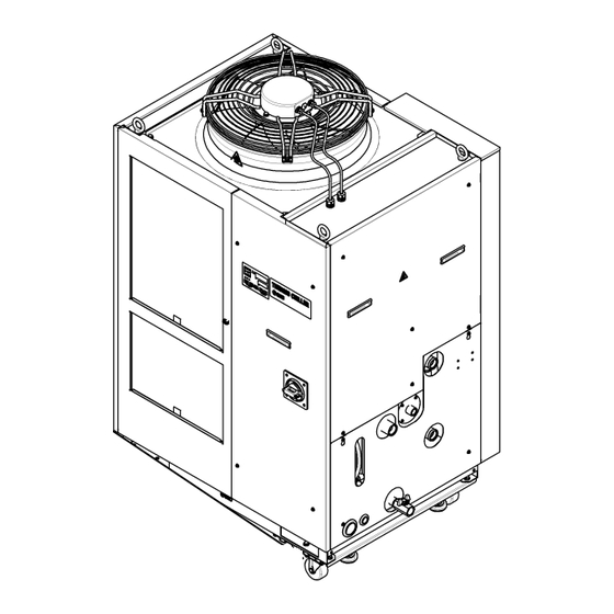
DOC1055019 Chapter 2 Name and Function of Parts 2.2 Name and Function of Parts 2.2.1 HRSF150/200-A-40 (Air cooled type) Option K [Fluid fill port] Fig. 2-3 Names of the parts Table 2-1: Accessory list 2 pcs. ① Alarm code list label (English 1 pc. -
Page 22: Hrsf150/200-W-40 (Water Cooled Type)
DOC1055019 Chapter 2 Name and Function of Parts 2.2.2 HRSF150/200-W-40 (Water cooled type) Option K [Fluid fill port] Fig. 2-4 Names of the parts Table 2-2: Accessory list 2 pcs. ① Alarm code list label (English 1 pc. /Japanese 1 pc.) 2 copies Operation manual (English 1 copy/Japanese 1... -
Page 23: Function Of Parts
DOC1055019 Chapter 2 Name and Function of Parts 2.3 Function of Parts The function of parts is as follows. Table 2-3: Function of parts Name Function Runs and stops the product and performs settings such as the circulating Operation display panel fluid temperature. -
Page 24: Operation Display Panel
DOC1055019 Chapter 2 Name and Function of Parts 2.4 Operation Display Panel The operation panel on the front of the product controls the basic operation of the product. Fig. 2-5 Operation display panel Table 2-4: Operation display panel Reference Description Function page Displays the temperature and pressure of the circulating... -
Page 25: Chapter 3 Transport And Setting Up
DOC1055019 Chapter 3 Transport and Setting Up Chapter 3 Transport and Setting Up ⚫ Only persons who have sufficient knowledge and experience about the product and system are allowed to transport and set up the product. ⚫ Especially pay attention to personal safety. 3.1 Transport The product is heavy and has potential danger at transport. -
Page 26: Transportation Using Forklift And Hanging
DOC1055019 Chapter 3 Transport and Setting Up 3.1.1 Transportation using forklift and hanging ⚫ This is a heavy product. (Refer to Table 3-1 Weight of the ⚫ product ⚫ Moving by forklift and slinging should be done by persons who have the licenses. -
Page 27: Transportation Using Casters
DOC1055019 Chapter 3 Transport and Setting Up 3.1.2 Transportation using casters In case of purchasing option A or the optional accessories, “Caster Adjuster- foot kit” (HRS-KS002) separately and after fastening it to the product. ⚫ This is a heavy product. (Refer to Table 3-1 Weight of the product). -
Page 28: Installation
DOC1055019 Chapter 3 Transport and Setting Up 3.2 Installation ⚫ Do not set up the product in places possibly exposed to leakage of flammable gas. Should any flammable gas stay around the product, the product may cause a fire. ⚫ This product uses flammable refrigerant. -
Page 29: Environment
DOC1055019 Chapter 3 Transport and Setting Up 3.2.1 Environment ⚫ The product must not be operated, installed, stored or transported in the following conditions. Potential malfunction or damage to the product may occur if these instructions are disregarded. ⚫ This product is not designed for clean room usage. The pump and ventilating fan inside the product generate particles. - Page 30 DOC1055019 Chapter 3 Transport and Setting Up ◼ Thermo-chiller installation in high altitude of 1000 meters or more Because of lower air density, the heat radiation efficiencies of the devices in the product will be lower in the location at altitude of 1000m or higher. For this reason, the maximum ambient temperature for the thermo-chiller operation and the cooling capacity will be reduced.
-
Page 31: Operation At Low Ambient Temperature Or Low Circulating Fluid Temperature
DOC1055019 Chapter 3 Transport and Setting Up 3.2.2 Operation at low ambient temperature or low circulating fluid temperature (1) Circulating fluid In order to avoid freezing of the circulating fluid, use aqueous solution of ethylene glycol. Ambient temperature (°C) Recommended circulating fluids 10 to 45 Tap water, ethylene glycol aqueous solution 15(wt)% -5 to 10... -
Page 32: Location
DOC1055019 Chapter 3 Transport and Setting Up 3.2.4 Location Do not install in a location which can be subjected to any of the conditions in “0 ”. The air cooled product radiates heat from the air vent of the cooling fan. If the product is operated with insufficient air ventilation the internal temperature can exceed 45 C, which can cause and affect the... - Page 33 DOC1055019 Chapter 3 Transport and Setting Up Table 3-2 Amount of radiation and required ventilation Required ventilation amount (m3/min) Heat Differential temp. of Differential temp. of Model radiation C between inside C between inside (kW) and outside of and outside of installation area installation area HRSF150-A-40-...
-
Page 34: Installation And Maintenance Space
DOC1055019 Chapter 3 Transport and Setting Up 3.2.5 Installation and maintenance space It is recommended to keep the space around the product shown in Fig. 3-3. Have an enough space for the ventilation for the product. Otherwise it may cause a lack of cooling capacity or/and stoppage of the product. Ensure there is enough space for maintenance. -
Page 35: Installation
DOC1055019 Chapter 3 Transport and Setting Up 3.3 Installation 3.3.1 Installation Install the product on a vibration free level floor. Prepare the M10 anchor bolts that are suitable for the material of the floor that the product will be installed on. Drive the anchor bolts in at least two places on the left and right sides of the product (four places in total). - Page 36 DOC1055019 Chapter 3 Transport and Setting Up ◼ Option A or “Caster Adjuster-foot kit” (HRS-KS002) In case of using “Caster Adjuster-foot kit”, be sure to use the adjuster foot to install on the floor. The adjuster foot is not earthquake-proof. If necessary make an earthquake-resistant measure on the customer side.
-
Page 37: Electrical Wiring
DOC1055019 Chapter 3 Transport and Setting Up 3.3.2 Electrical wiring ⚫ Do not modify the internal electrical wiring of the product. Incorrect wiring may cause electric shock or fire. Also, modifying the internal wiring will void the product’s warranty. ⚫ NEVER connect the ground to water line, gas pipe or lightning conductor. - Page 38 DOC1055019 Chapter 3 Transport and Setting Up ◼ Power supply specifications, power supply cable and earth leakage breaker Prepare the power supply shown in the following table. For the connection between the product and power supply, use the power supply cable and earth leakage breaker shown below. An earth leakage breaker must be mounted to a position where the breaker is easily accessible and close to the thermo- chiller.
-
Page 39: Preparation And Wiring Of Power Supply Cable
DOC1055019 Chapter 3 Transport and Setting Up 3.3.3 Preparation and wiring of power supply cable ⚫ The electrical facilities should be installed and wired in accordance with local laws and regulations of each country and by a person who has knowledge and experience. ⚫... - Page 40 DOC1055019 Chapter 3 Transport and Setting Up A breaker that has the operating characteristic below is installed. Please use a breaker that has the same or longer operating time as/than this for the customer side (upstream side). If it has a shorter operating time, there is a possibility of accidental breaker trip due to the internal motors’...
-
Page 41: Preparation For Operation
DOC1055019 Chapter 3 Transport and Setting Up ◼ Preparation for operation Remove four screws to remove the front panel for the electrical unit. Front panel for the electrical unit Note: Turn off the earth leakage breaker. The front panel of the electrical unit cannot be removed without turning off the... - Page 42 DOC1055019 Chapter 3 Transport and Setting Up Hold the handle and pull up the front panel of the electrical unit, and remove it. Handle View A Fig. 3-8 Remove the front panel for the electrical unit (This drawing shows air cooled type.) Handle View A Fig.
- Page 43 DOC1055019 Chapter 3 Transport and Setting Up Connect the power supply cable and the ground cable as shown in the figure below. View A L1 L2 L3 PE Inlet of the power supply cable Note: Prepare a cable tie. Mount for cable tie Fasten the power cable to the mount on the base with the cable tie.
-
Page 44: Contact Input/Output Communicatin Wiring
DOC1055019 Chapter 3 Transport and Setting Up 3.3.4 Contact input/output communicatin wiring Be sure to lock out and tag out the breaker of the facility power supply (the user’s machine power supply) before wiring. ⚫ Use the cable and terminal that are specified. ⚫... -
Page 45: Specification
DOC1055019 Chapter 3 Transport and Setting Up Table 3-6 Power supply, contact specifications Name Terminal No. Specification 5, 6, 7 Power supply (24 VDC) 24 VDC ±10 % 500 mA MAX output 13,14, 15 (24 V COM) - Run/Stop signal input Contact input (Contact input signal 1) - External switch signal... - Page 46 DOC1055019 Chapter 3 Transport and Setting Up Connect the signal cable and switch to the terminal as shown below. (This wiring is an example. Refer to Operation Manual Communication Function for more details.) Switch Terminal No. 5 Terminal No.13 Terminal No. 3 Mount for cable tie Note: Prepare a cable tie.
-
Page 47: Wiring Of External Switch Signal Input
DOC1055019 Chapter 3 Transport and Setting Up 3.3.6 Wiring of external switch signal input This product can be monitored by sampling the signal of the external switch prepared by the user. Table 3-7 Power supply, contact specifications Name Terminal No. Specification 5, 6, 7 (24 VDC) Power supply output... - Page 48 DOC1055019 Chapter 3 Transport and Setting Up Prepare the flow switch described in the Table 3-9 (sold separately). Depending on the external switch output type, connect the wire the switch to the terminals for contact input signal as shown below. (This is an example of wiring. Refer to the Operation Manual Communication Function for further details.) Flow switch...
-
Page 49: Setting Items
DOC1055019 Chapter 3 Transport and Setting Up ◼ Setting items Table 3-10 shows the setting items of the external switch. For details, refer to “5.21 Communication Function”. Table 3-10 Setting list of the external switch Initial value Reference Display Item Example Category (Default setting) -
Page 50: Wiring Of Contact Output Signal
DOC1055019 Chapter 3 Transport and Setting Up 3.3.7 Wiring of contact output signal Contact output signals are the signals that output the status of this product. Contact specification of each signal output is shown below. Be sure to turn OFF the breaker of the facility power supply (the user's machine power supply) before wiring. -
Page 51: Communication Wiring
DOC1055019 Chapter 3 Transport and Setting Up 3.3.8 RS-485 communication wiring Serial communication RS-485, operation Start/Stop, setting and reading of circulating fluid temperature, and reading of alarm condition can be performed by remote control. Refer to Operation Manual Communication Function for more details. ◼... -
Page 52: Rs-232C Communication Wiring
DOC1055019 Chapter 3 Transport and Setting Up 3.3.9 RS-232C communication wiring Serial communication RS-232C, operation start/stop, setting and reading of circulating fluid temperature, and reading of alarm condition can be performed by remote control. Refer to Operation Manual Communication Function for more details. ◼... -
Page 53: Piping
DOC1055019 Chapter 3 Transport and Setting Up 3.4 Piping ⚫ Connect piping firmly. Incorrect piping might cause leakage of supplied or drained fluid and wet surrounding area and facility. ⚫ Use caution not to allow dust and foreign matter to enter the water circuit, etc. - Page 54 DOC1055019 Chapter 3 Transport and Setting Up ◼ Piping port size Table 3-12 Piping port size Recommended Recommended piping Description Port size tightening torque specifications 36 to 38Nm 1.0 MPa or more Circulating fluid outlet port 36 to 38Nm 1.0 MPa or more Circulating fluid return port 36 to 38Nm 1.0 MPa or more.
-
Page 55: How To Connect To The Drain Port
DOC1055019 Chapter 3 Transport and Setting Up ◼ How to connect piping Hold the each piping port with a wrench and tighten the piping. Connection port Sealant Note: When using the Y strainer of the accessory, fasten it on the return port. - Page 56 DOC1055019 Chapter 3 Transport and Setting Up ◼ Recommended piping circuit Fig. 3-18 Recommended piping circuit Description Size Recommended part no. Note Valve Rc1/2 To prevent liquid spillage from the customer's piping or overflow from the tank during maintenance work. Valve Y-strainer Accessory...
-
Page 57: Circulating Fluid Supply
DOC1055019 Chapter 3 Transport and Setting Up 3.5 Circulating Fluid Supply 3.5.1 Automatic water fill function ⚫ When clear water is used, refer to “7.1 Water Quality Management”. ⚫ When ethylene glycol aqueous solution is used, dilute pure ethylene glycol with water. Refer to "3.2.2 Operation at low ambient temperature or low circulating fluid temperature"... - Page 58 DOC1055019 Chapter 3 Transport and Setting Up ◼ Ethylene glycol aqueous solution When ethylene glycol aqueous solution is used, prepare the ethylene glycol aqueous solution separately. Refer to "3.2.2 Operation at low ambient temperature or low circulating fluid temperature" for the concentration of the ethylene glycol aqueous solution. To control the concentration of the ethylene glycol aqueous solution, a densitometer is available (sold separately) from SMC.
-
Page 59: Fluid Supply Without Using The Automatic Water Fill Function
DOC1055019 Chapter 3 Transport and Setting Up 3.5.2 Fluid supply without using the automatic water fill function To supply the circulating fluid without using automatic water fill function, remove the upper panel on the right side, and supply the fluid to the water fill port on top of the tank. - Page 60 DOC1055019 Chapter 3 Transport and Setting Up Supply the circulating fluid to the water fill port. ⚫ Confirm that the fluid level is between “HIGH” and “LOW” levels of the fluid level gauge. If it exceeds the specified level, the circulating fluid will overflow.
-
Page 61: Option K "Water Fill Port
DOC1055019 Chapter 3 Transport and Setting Up Option K “Water fill port” 3.5.3 ⚫ Confirm that the fluid level is between “HIGH” and “LOW” levels of the fluid level gauge. If it exceeds the specified level, the circulating fluid will overflow. ⚫... - Page 62 DOC1055019 Chapter 3 Transport and Setting Up 3.5 Circulating Fluid Supply HRSF Series 3-38...
-
Page 63: Chapter 4 Starting The Product
DOC1055019 Chapter 4 Starting the Product Chapter 4 Starting the Product Only people who have sufficient knowledge and experience about the product and its accessories are allowed to start and stop the product. Before Starting Check the following points before starting the product. ◼... - Page 64 DOC1055019 Chapter 4 Starting the Product ⚫ Facility water quality must satisfy the quality standard shown in ” 7.1 Water Quality Management” and the conditions shown in “8.1 Specifications”. ⚫ If the facility water supply pressur is too high (over 0.5 MPa), it will cause water leakage.
-
Page 65: Preparation For Start
DOC1055019 Chapter 4 Starting the Product 4.2 Preparation for Start 4.2.1 Power supply Turn ON the breaker of the user’s power supply. When the product is switched ON, the operation panel display operates as shown below: ⚫ The initial screen (HELLO screen) is displayed for 8 seconds on the operation display panel. -
Page 66: Setting Of Circulating Fluid Temperature
DOC1055019 Chapter 4 Starting the Product 4.2.2 Setting of circulating fluid temperature Press the [▼] or [▲] key on the operation panel to change the SV to the required value. When setting the circulating fluid temperature by communication, refer to Operation Manual Communication Function. -
Page 67: Preparation Of Circulating Fluid Supply To User's Equipment
DOC1055019 Chapter 4 Starting the Product 4.3 Preparation of Circulating Fluid Supply to User’s Equipment Circulating fluid is supplied only inside of the product at the time of installation of the thermo-chiller. When the product starts operation in this condition, circulating fluid level will be reduced as the fluid in the level gauge goes down due to the fluid supply to the user's equipment from the thermo-chiller, and the additional fluid needs to be supplied to the thermo-chiller. - Page 68 DOC1055019 Chapter 4 Starting the Product Press the [RESET] key (press the [▼] and [▲] keys simultaneously) to stop the alarm buzzer. Blinks Press these keys simultaneously. Turns ON Fig. 4-5 How to stop the alarm buzzer Reset alarms on the ”Alarm menu” screen. Alarm reset is not accepted from any screen except the "Alarm menu"...
- Page 69 DOC1055019 Chapter 4 Starting the Product Press the [RESET] key (press the [▼] and [▲] keys simultaneously) to reset the alarm. Pressing these keys at the same time resets the alarm (low level in tank) and turns OFF the [ALARM] LED (red) and the [ ] LED.
-
Page 70: Operation Start And Stop
DOC1055019 Chapter 4 Starting the Product Operation Start and Stop 4.4.1 Starting the product Allow at least five minutes before restarting the product. Before starting, check the items specified in “4.1 Before Starting” If any alarm light remains ON, refer to “Chapter 6 Alarm Notification and Troubleshooting”... -
Page 71: Stopping The Product
DOC1055019 Chapter 4 Starting the Product 4.4.2 Stopping the product Press the [RUN/STOP] key on the operation panel. The [RUN] light on the operation panel blinks green at 1 second intervals and continues operation to prepare to stop. After approximately 20 seconds, the [RUN] light turns OFF and the operation stops completely. Blinks Turns OFF 等... -
Page 72: Check Items During Startup
DOC1055019 Chapter 4 Starting the Product 4.5 Check Items during Startup Check the following items after starting the product. When any abnormality is found, press the [STOP] key to stop the product operation, and then turn OFF the breaker of the user’s power supply. -
Page 73: Chapter 5 Display And Setting Of Various Functions
DOC1055019 Chapter 5 Display and Setting of Various Functions Chapter 5 Display and Setting of Various Functions Read and understand this manual carefully before changing the settings. 5.1 List of Functions The product can have the displays and settings shown in Table 5.1-1 List of functions. -
Page 74: Function
DOC1055019 Chapter 5 Display and Setting of Various Functions 5.2 Function 5.2.1 Key operations Fig. 5-1 “Key operation (1/2)” and “Key operation (2/2)” show the key operations of the thermo-chiller. By pressing the [SEL] key for 1 second, the PV display blinks and the function of [SEL] key is reversed to allow reverse scrolling through the menu. - Page 75 DOC1055019 Chapter 5 Display and Setting of Various Functions MENU MENU MENU Communication Alarm setting menu setting menu Contact input Alarm Unused Communicati signal 1 Delay buzzer on mode MENU MENU timer (time sound delay) of Press the Press the 2 sec.
-
Page 76: List Of Parameters
DOC1055019 Chapter 5 Display and Setting of Various Functions 5.2.2 List of parameters “Table 5.2-1 List of parameters (1/3)” to “Table 5.2-3 List of parameters (3/3)” show the parameters of the thermo-chiller. Table 5.2-1 List of parameters (1/3) Reference Display Content Default Category... - Page 77 DOC1055019 Chapter 5 Display and Setting of Various Functions Table 5.2-2 List of parameters (2/3) Reference Display Content Default Category page Pump operation mode setting HRSF150/200-A HRSF150/200-W 0.45MPa (----) 5.15 Circulating fluid discharge pressure setting HRSF150/200-W-T 0.50MPa (----) Setting Pump operation frequency setting ---- (30) menu Warming up function...
-
Page 78: Alarm Setting Menu
DOC1055019 Chapter 5 Display and Setting of Various Functions Table 5.2-3 List of parameters (3/3) Reference Display Content Default Category page ---- Unused ---- Unused Temperature alarm monitoring method ---- (0) Operation setting for the monitoring start timer Threshold time setting for the range over detection timer P.RUN Alarm settings for the compressor Operation setting when "Circulating fluid discharge... -
Page 79: Main Display
DOC1055019 Chapter 5 Display and Setting of Various Functions 5.3 Main Display 5.3.1 Main display The current temperature and the set temperature of the circulating fluid are shown on the main display, and the main display allows the set temperature to be changed. -
Page 80: Alarm Menu
DOC1055019 Chapter 5 Display and Setting of Various Functions 5.4 Alarm Menu 5.4.1 Alarm menu The alarm menu display appears when an alarm is generated. The alarm menu is not accessible when no alarm has been generated. Refer to “Chapter 6 Alarm Notification and Troubleshooting” for details of the alarms. 5.4.2 Items shown on the alarm menu display The alarm menu display appears when an alarm is being generated. -
Page 81: Check Monitor Menu
DOC1055019 Chapter 5 Display and Setting of Various Functions 5.5 Check Monitor Menu 5.5.1 Check monitor menu As a part of the daily inspection, the temperature, pressure and accumulated operating time can be checked. Please use this for confirmation of your daily inspection. 5.5.2 Checking with the check monitor menu The table below explains the check items in the check monitor menu. - Page 82 DOC1055019 Chapter 5 Display and Setting of Various Functions Checking: Circulating fluid return temperature Press the [SEL] key once. Display of the circulating fluid temperature returned to the return port appears on the digital display. Displays the circulating fluid temperature returning from the user’s equipment. Checking: Inlet refrigerant temperature to the compressor.
- Page 83 DOC1055019 Chapter 5 Display and Setting of Various Functions Checking: Accumulated operating time of the pump Press the [SEL] key once. Display of the accumulated operating time of the pump appears on the digital display. Refer to the table below for details of the display. Table 5.5-2 Time display Accumulated time Displayed value...
- Page 84 DOC1055019 Chapter 5 Display and Setting of Various Functions Checking: Accumulated operating time of the compressor Press the [SEL] key once. Display of the accumulated operating time of the compressor appears on the digital display. Refer to “Table 5.5-2 Time display” for the display. AL30 Compressor maintenance alarm is generated when the accumulated operating time of the compressor reaches 30,000 hours ( ) (when set to “A.RUN”).
-
Page 85: Key-Lock
DOC1055019 Chapter 5 Display and Setting of Various Functions 5.6 Key-lock 5.6.1 Key-lock The keys can be locked to prevent the settings being changed by an operator error. Operation can be started / stopped by operating the “RUN/STOP” key even when the key-lock is being activated. If you try to change the set value with the “▲”... -
Page 86: Key-Lock
DOC1055019 Chapter 5 Display and Setting of Various Functions 5.6.2 Key-lock setting / checking The table below explains the setting items of the key-lock function and the initial values. Table 5.6-1 Set items for key-lock Display Item Contents Default Sets the key-lock function ON. Key-lock When the key-lock function is set ON, no other settings are available. -
Page 87: Run Timer And Stop Timer Function
DOC1055019 Chapter 5 Display and Setting of Various Functions Run Timer and Stop Timer Function 5.7.1 Run timer and stop timer function This function starts or stops operation of the product automatically when the set time has passed. The time can be set according to the user’s working hours. - Page 88 DOC1055019 Chapter 5 Display and Setting of Various Functions Timer setting examples Run timer Set to start 3 hours later ・・・ Stopped Operating ↑ Starts operating Stop timer Set to stop 3 hours later ・・・ Operating Stopped ↑Stops operating Run timer Stop timer Set to start 2 hours later, ・・・...
-
Page 89: Setting And Checking Of Run Timer And Stop Timer Function
DOC1055019 Chapter 5 Display and Setting of Various Functions 5.7.2 Setting and checking of run timer and stop timer function The table below explains the setting items of the run/stop timer and the initial values. Table 5.7-1 Setting of run timer and stop timer Display Item Contents... - Page 90 DOC1055019 Chapter 5 Display and Setting of Various Functions Setting/checking: Stop timer Press the [SEL] key once. Setting screen of the stop timer appears on the digital display. Select stop timer with the [▲] key or the [▼] key, and press [SEL] key to enter. Table 5.7-3 Setting of the stop timer Set value Explanation...
-
Page 91: Ready Completion (Temp Ready) Signal
DOC1055019 Chapter 5 Display and Setting of Various Functions 5.8 Ready Completion (TEMP READY) Signal 5.8.1 Ready completion (TEMP READY) signal This function sets a bandwidth for the set circulating fluid temperature (range between the upper and lower limit temperatures) to notify the user by communication that the circulating fluid temperature has reached the band range. -
Page 92: Ready Completion (Temp Ready) Signal Setting / Checking
DOC1055019 Chapter 5 Display and Setting of Various Functions 5.8.2 Ready completion (TEMP READY) signal setting / checking The table below shows explanation and default of the set items for ready completion (TEMP READY) signal. Table 5.8-1 Set items for ready completion (TEMP READY) signal Display Item Content... - Page 93 DOC1055019 Chapter 5 Display and Setting of Various Functions Select READY bandwidth with [▲] key or [▼] key, and enter by pressing the [SEL] key. Table 5.8-3 Set value for READY mode Set value Explanation Default Sets READY bandwidth (range between the upper and lower limit temperatures) for the set circulating fluid temperature.
-
Page 94: Offset Function
DOC1055019 Chapter 5 Display and Setting of Various Functions 5.9 Offset Function 5.9.1 Offset function This is a function that controls the "circulating fluid display temperature" and the "target temperature for chiller temperature control" by shifting the temperature for the set offset value. This product has three different modes of offset functions (MODE 1 to 3). -
Page 95: Usage Example Of Offset Function
DOC1055019 Chapter 5 Display and Setting of Various Functions 5.9.2 Usage example of offset function Suppose that the circulating fluid discharge temperature of this thermo- chiller is 30 C and the circulating fluid temperature that enters the user's equipment is 29 C due to temperature drop while it is transferred to the user's equipment in the piping: This product... - Page 96 DOC1055019 Chapter 5 Display and Setting of Various Functions ■ When only the "displayed circulating fluid temperature" needs to be the same as the circulating temperature supplied to the user's equipment: Use "MODE 2" of the offset function, and set the offset temperature to "-1.0" 1.
-
Page 97: Setting/Checking Of Offset Function
DOC1055019 Chapter 5 Display and Setting of Various Functions 5.9.3 Setting/checking of offset function The table below shows the set items of the offset function and the default values. Table 5.9-2 Set items for offset function Display Item Contents Default Offset mode Offset mode is set ON/OFF. - Page 98 DOC1055019 Chapter 5 Display and Setting of Various Functions Setting/Checking: Offset temperature Press the [SEL] key once. Setting screen of offset temperature appears on the digital display. Set offset temperature with [▲] key or [▼] key, and press [SEL] key to enter. Table 5.9-4 Offset temperature setting Set value Explanation...
-
Page 99: Operation Restoration After Power Failure
DOC1055019 Chapter 5 Display and Setting of Various Functions 5.10 Operation Restoration after Power Failure 5.10.1 Operation restoration function after power failure When the power supply is cut due to power failure, etc., this function restarts the operation when the power supply restores, retaining the conditions before the power cut. -
Page 100: Setting/Checking Of The Operation Restoration Function
DOC1055019 Chapter 5 Display and Setting of Various Functions 5.10.2 Setting/checking of the operation restoration function The table below shows the setting items of the operation restoration after power failure function and the default setting. Table 5.10-1 Set item for operation restoration after power failure function Display Item Contents... -
Page 101: Anti-Freezing Function
DOC1055019 Chapter 5 Display and Setting of Various Functions 5.11 Anti-freezing Function 5.11.1 Anti-freezing function Keep the power supply ON for this function. This function does not start when the power is OFF. This function prevents freezing of the circulating fluid while the product stops operation in the winter season with heat generated by automatically operating the pump. -
Page 102: Anti-Freezing Function
DOC1055019 Chapter 5 Display and Setting of Various Functions 5.11.2 Setting/checking of anti-freezing function The table below shows the set item of the anti-freezing function and the default setting. Table 5.11-1 Set item for anti-freezing function Display Item Contents Default Anti-freezing Sets anti-freezing function ON/OFF. -
Page 103: Key Operation Sound Setting
DOC1055019 Chapter 5 Display and Setting of Various Functions 5.12 Key Operation Sound Setting 5.12.1 Key operation sound setting Operation sound (click sound) of the keys on the operation panel can be set ON/OFF. Default setting is key operation sound “ON”. 5.12.2 Setting/checking of the key operation sound The table below shows the set item for key operation sound and the default setting. -
Page 104: Data Reset Fanction
DOC1055019 Chapter 5 Display and Setting of Various Functions 5.13 Data reset fanction 5.13.1 Data reset function Resets the values set by user to the default values. Note that the accumulated operating time will not be reset. This function resets all the set values. Use caution when operating this function. -
Page 105: Accumulated Operating Time Reset Function
DOC1055019 Chapter 5 Display and Setting of Various Functions 5.14 Accumulated Operating Time Reset Function 5.14.1 Accumulated operating time reset function The alarms shown below will be generated to notify the maintenance timing. The thermo-chiller does not stop operation for these alarms. ⚫... - Page 106 DOC1055019 Chapter 5 Display and Setting of Various Functions Press the [SEL] key 14 times. Resetting screen of the pump accumulated operating time appears on the digital display. with [▲] key or [▼] key, and press [SEL] key to enter. Select Select and press [SEL] key to enter, and the accumulated operating time of the pump will be reset.
- Page 107 DOC1055019 Chapter 5 Display and Setting of Various Functions Reset of accumulated operating time Press and hold the [MENU] key for approximately 2 seconds. Repeat pressing the key until the key-lock setting screen [ ] appears on the digital display. Press and Press and hold [MENU]...
- Page 108 DOC1055019 Chapter 5 Display and Setting of Various Functions with [▲] key or [▼] key, and press [SEL] key to enter. Select Select and press [SEL] key to enter, and the accumulated operating time of the dust-proof filter will be reset. The display returns to the main menu. Table 5.14-5 Reset setting Set value Explanation...
-
Page 109: Pump Operation Mode Setting
DOC1055019 Chapter 5 Display and Setting of Various Functions 5.15 Pump Operation Mode Setting 5.15.1 Pump operation mode Pump operation mode can be selected from the two modes shown below. ●Pressure control mode The pump in this product automatically controls the circulating fluid discharge pressure to be the set pressure. - Page 110 DOC1055019 Chapter 5 Display and Setting of Various Functions Press and hold the [MENU] key for approximately 2 seconds. Repeat pressing the key until the key-lock setting screen [ ] appears on the digital display. Press and Press and hold [MENU] hold [MENU] key.
- Page 111 DOC1055019 Chapter 5 Display and Setting of Various Functions Setting: Pump operation frequency Press the [SEL] key once. Setting screen of the pump operation frequency appears on the digital display. Set circulating fluid discharge pressure with [▲] key or [▼] key, and press [SEL] key to enter.
-
Page 112: Warming Up Function
DOC1055019 Chapter 5 Display and Setting of Various Functions 5.16 Warming Up Function 5.16.1 Warming up function Keep the power supply ON for this function. This function does not operate when the power is OFF. This function maintains the circulating fluid temperature to the set warming- up temperature with heat generated by automatically operating the pump in the winter season or at night. -
Page 113: Setting/Checking Of Warming Up Function
DOC1055019 Chapter 5 Display and Setting of Various Functions 5.16.2 Setting/checking of warming up function The table below shows the setting items of the warming up function and the default setting. Table 5.16-1 Set item for warming up function Display Item Content Default... - Page 114 DOC1055019 Chapter 5 Display and Setting of Various Functions Set the warming up temperature with [▲] key or [▼] key, and press [SEL] key to enter. Table 5.16-3 Setting of warming up temperature Set value Explanation Default Setting and checking are not available when the warming up function is set OFF.
-
Page 115: Anti-Snow Coverage Function
DOC1055019 Chapter 5 Display and Setting of Various Functions 5.17 Anti-Snow Coverage Function 5.17.1 Anti-snow coverage function Keep the power supply ON for this function. This function does not operate when the power is OFF. This function does not operate for water-cooled type. This function prevents snow coverage on the exhaust port on top of the product during the winter time by automatically operating the fan periodically. -
Page 116: Anti-Snow Coverage Function
DOC1055019 Chapter 5 Display and Setting of Various Functions 5.17.2 Setting/checking of anti-snow coverage function The table below shows the set item of the anti-snow coverage function and the default setting. Table 5.17-1 Set item for anti-snow coverage function Display Item Content Default... -
Page 117: Fan Motor Output Upper Limit Setting
DOC1055019 Chapter 5 Display and Setting of Various Functions 5.18 Fan motor output upper limit setting The table below shows the set item of the fan motor output upper limit and the default setting. Table5.18-1 Set item for fan motor output upper limit Display Item Contents... -
Page 118: Alarm Buzzer Sound Setting
DOC1055019 Chapter 5 Display and Setting of Various Functions 5.19 Alarm Buzzer Sound Setting 5.19.1 Alarm buzzer sound setting This sets whether a warning sound is made or not when alarm signal is output. The default setting is buzzer sound ON. 5.19.2 Setting/checking of alarm buzzer sound The table below shows the set item of the alarm buzzer sound and the default setting. -
Page 119: Alarm Customizing Function
DOC1055019 Chapter 5 Display and Setting of Various Functions 5.20 Alarm Customizing Function 5.20.1 Alarm customizing function Operation and trigger level when an alarm signal is output can be customized. Perform settings depending on the application of the user. Refer to “Table 5.20-1 Default alarm settings and customizing (1/4)”... - Page 120 DOC1055019 Chapter 5 Display and Setting of Various Functions Table 5.20-2 Default alarm settings and customizing (2/4) 1. Operation during alarm 2. Threshold for alarm generation and generation other settings Code Alarm name Display Display Default Settable range Set temperature 1.0 to 34.0 3 (----)
- Page 121 DOC1055019 Chapter 5 Display and Setting of Various Functions Table 5.20-3 Default Alarm setting and customizing (3/4) 1. Operation during alarm 2. Threshold for alarm generation and generation other settings Code Alarm name Display Display Default Settable range Compressor running ●...
- Page 122 DOC1055019 Chapter 5 Display and Setting of Various Functions Table 5.20-4 Default alarm settings and customizing (4/4) 1. Operation during alarm 2. Threshold for alarm generation generation and other settings Code Alarm name Settable Display Display Default range Internal unit fan ○...
-
Page 123: Alarm Customizing Function
DOC1055019 Chapter 5 Display and Setting of Various Functions 5.20.2 Setting and checking of the alarm customizing function The table below shows the set items of the alarm customizing function and the default settings. Table 5.20-5 Default settings of the alarm customizing function (1/3) Alarm 1 Display... - Page 124 DOC1055019 Chapter 5 Display and Setting of Various Functions Table 5.20-6 Default settings of the alarm customizing function (2/3) Alarm Default Display Content Change Code Alarm name Setting function for Contact input 1 signal Product operation while the AL31 A.STP "Contact input detection alarm is being generated...
- Page 125 DOC1055019 Chapter 5 Display and Setting of Various Functions Table 5.20-7 Default settings of the alarm customizing function (3/3) Alarm Alarm Display Content Default Display Code Alarm name Operation setting when "Circulating fluid Circulating fluid Product operation AL25 A.STP discharge pressure discharge pressure while the alarm is sensor error"...
- Page 126 DOC1055019 Chapter 5 Display and Setting of Various Functions Set the product operation when "Low level in tank" alarm is generated with [▲] key or [▼] key, and press [SEL] key to enter. Table 5.20-8 Product operation setting when “Low level in tank” alarm is generated Set value Explanation Default...
- Page 127 DOC1055019 Chapter 5 Display and Setting of Various Functions Set the threshold detection temperature for "Circulating fluid discharge temp. rise" alarm generation with [▲] key or [▼] key, and press [SEL] key to enter. Table 5.20-10 Threshold detection temperature setting for "Circulating fluid discharge temp. rise" alarm generation Set value Explanation Default...
- Page 128 DOC1055019 Chapter 5 Display and Setting of Various Functions Set the threshold detecting temperature for "Circulating fluid discharge temp. drop" alarm generation with [▲] key or [▼] key, and press [SEL] key to enter. Table 5.20-12 Threshold detecting temperature for "Circulating fluid discharge temp. drop" alarm Set value Explanation Default...
- Page 129 DOC1055019 Chapter 5 Display and Setting of Various Functions Set the threshold detection pressure for "Circulating fluid discharge pressure rise" alarm generation with [▲] key or [▼] key, and press [SEL] key to enter. Table 5.20-14 Threshold detecting pressure setting for "Circulating fluid discharge pressure rise" alarm Set value Explanation Default...
- Page 130 DOC1055019 Chapter 5 Display and Setting of Various Functions Set the threshold detection pressure for "Circulating fluid discharge pressure drop" alarm generation with [▲] key or [▼] key, and press [SEL] key to enter. Table 5.20-16 Threshold detecting pressure setting for "Circulating fluid discharge pressure drop" alarm generation Set value Explanation Default...
- Page 131 DOC1055019 Chapter 5 Display and Setting of Various Functions Set monitoring time for "Communication error" alarm with [▲] key or [▼] key, and confirm by pressing “SEL”. Table 5.20-18 Monitoring time for "Communication error" alarm setting Set value Explanation Default Setting/checking of the alarm is impossible when the "AS11 Communication error"...
- Page 132 DOC1055019 Chapter 5 Display and Setting of Various Functions Set the product operation when "Contact input 2 signal detection" alarm is generated with [▲] key or [▼] key, and press [SEL] key to enter. Table 5.20-20 Operation setting when "Contact input 2 signal detection" alarm is generated Set value Explanation Default...
- Page 133 DOC1055019 Chapter 5 Display and Setting of Various Functions Set temperature alarm monitoring method with [▲] key or [▼] key, and press [SEL] key to enter. Table 5.20-22 Setting of temperature alarm monitoring method Set value Item Explanation Default Alarm monitoring starts at the same time as the product is turned ON.
- Page 134 DOC1055019 Chapter 5 Display and Setting of Various Functions Set monitoring start timer with the [▲] key or the [▼] key, and press [SEL] key to enter. Table 5.20-23 Setting of the monitoring start timer Set value Explanation Default Setting and checking are impossible when "0: Continuous monitoring"...
-
Page 135: Setting Of Temperature Alarm Monitoring Method And Alarm Generation Timing
DOC1055019 Chapter 5 Display and Setting of Various Functions 5.20.3 Setting of temperature alarm monitoring method and alarm generation timing Examples of temperature alarm monitoring method setting and alarm generation timing are shown below. When "Automatic monitoring" is selected; ◼ [1] Circulating fluid temperature when starting operation: Approximately 20 Circulating fluid set temperature : 15... - Page 136 DOC1055019 Chapter 5 Display and Setting of Various Functions ◼ When "Automatic monitoring + Monitoring start timer" is selected [1] Circulating fluid temperature when starting operation: Approximately 20 Circulating fluid set temperature : 15 [3] "AS.21: Temperature alarm monitoring method": Select "Automatic monitoring + Monitoring start timer".
- Page 137 DOC1055019 Chapter 5 Display and Setting of Various Functions Setting/Checking: Operation when compressor related alarms are generated Press the [SEL] key once. Setting screen of the product operation when compressor related alarms are generated appears on the digital display. Set the product operation when the compressor related errors are generated with the [▲] key or [▼] key.
- Page 138 DOC1055019 Chapter 5 Display and Setting of Various Functions Setting/Checking: Operation setting when "Circulating fluid discharge pressure sensor error" alarm is generated Press the [SEL] key once. Operation setting screen when "Circulating fluid discharge pressure sensor failure" alarm is generated appears on the digital display. Set the product operation when "Circulating fluid discharge pressure sensor failure"...
- Page 139 DOC1055019 Chapter 5 Display and Setting of Various Functions Setting/Checking: Operation setting when "Fan maintenance" alarm is generated Press the [SEL] key once. Operation setting screen when "Fan maintenance" alarm is generated appears on the digital display. Set the product operation when "Fan maintenance" alarm is generated with [▲] key or [▼] key, and press [SEL] key to enter.
- Page 140 DOC1055019 Chapter 5 Display and Setting of Various Functions Setting/Checking: Operation setting when "Dust-proof filter maintenance" alarm is generated Press the [SEL] key once. Operation setting screen when "Dust-proof filter maintenance" alarm is generated appears on the digital display. Set the product operation when "Dust-proof filter maintenance" alarm is generated with [▲] key or [▼] key, and press [SEL] key to enter.
- Page 141 DOC1055019 Chapter 5 Display and Setting of Various Functions Setting/Checking: Monitoring time for maintenance of dustproof filter Press the [SEL] key once. Setting screen of the monitoring time before "Dust-proof filter maintenance" alarm is generated is displayed on the digital display. Set the monitoring time before the "Dust-proof filter maintenance"...
-
Page 142: Communication Function
DOC1055019 Chapter 5 Display and Setting of Various Functions 5.21 Communication Function 5.21.1 Communication function Contact input/output and serial communication can be performed. Refer to the Operation Manual Communication Function for more details. 5.21.2 Setting/checking of communication function The table below shows the set items of the communication function and default settings. - Page 143 DOC1055019 Chapter 5 Display and Setting of Various Functions Setting/Checking: Communication mode Press and hold the [MENU] key for approximately 2 seconds. Repeat pressing the key until the communication mode setting screen [ ] appears on the digital display. Press and Press and Press and hold [MENU]...
- Page 144 DOC1055019 Chapter 5 Display and Setting of Various Functions Select a serial communication protocol with [▲] key or [▼] key, and press [SEL] key to enter. Table 5.21-3 Setting of serial communication protocol Set value Explanation Default MODBUS protocol ✓ Simple communication protocol 1 1 Simple communication protocol 2...
- Page 145 DOC1055019 Chapter 5 Display and Setting of Various Functions Setting/Checking: Device addresses (MODBUS) Press the [SEL] key once. Setting screen of device addresses (MODBUS) is displayed on the digital display. Set device addresses (MODBUS) with [▲] key or [▼] key, and press [SEL] key to enter.
- Page 146 DOC1055019 Chapter 5 Display and Setting of Various Functions Set device addresses (simple communication protocol) with [▲] key or [▼] key, and press [SEL] key to enter. Table 5.21-8 Setting of device addresses Set value Explanation Default Setting/checking is possible only when the serial protocol setting is simple communication protocol.
- Page 147 DOC1055019 Chapter 5 Display and Setting of Various Functions Set BCC (simple communication protocol) with [▲] key or [▼] key, and press [SEL] key to enter. Table 5.21-10 BCC setting Set value Explanation Default Setting/checking is possible only when the serial protocol setting is simple communication protocol.
- Page 148 DOC1055019 Chapter 5 Display and Setting of Various Functions Perform setting for parity check (simple communication protocol) with [▲] key or [▼] key, and press [SEL] key to enter. Table 5.21-12 Parity check setting Set value Explanation Default Setting/checking is possible only when the serial protocol setting is simple communication protocol.
- Page 149 DOC1055019 Chapter 5 Display and Setting of Various Functions Set responce delay time (simple communication protocol) with [▲] key or [▼] key, and press [SEL] key to enter. Table 5.21-14 Setting of response delay time Set value Explanation Default Setting/checking is possible only when the serial protocol setting is simple communication protocol.
- Page 150 DOC1055019 Chapter 5 Display and Setting of Various Functions Perform setting for the contact input signal 1 with [▲] key or [▼] key, and press [SEL] key to enter. Table 5.21-16 Setting for contact input signal 1 Set value Explanation Default No signal input Run/Stop signal input...
- Page 151 DOC1055019 Chapter 5 Display and Setting of Various Functions Set time delay for the contact input signal 1 delay timer for reading with [▲] key or [▼] key, and press [SEL] key to enter. Table 5.21-18 Setting of time delay for contact input signal delay timer for reading Set value Explanation Default...
- Page 152 DOC1055019 Chapter 5 Display and Setting of Various Functions Perform setting of the contact input signal 2 with [▲] key or [▼] key, and press [SEL] key to enter. Table 5.21-20 Setting of the contact input signal 2 Set value Explanation Default No signal input...
- Page 153 DOC1055019 Chapter 5 Display and Setting of Various Functions Set time delay for the contact input signal 2 delay timer for reading with [▲] key or [▼] key, and press [SEL] key to enter. Table 5.21-22 Setting of time delay for the contact input signal 2 delay timer for reading Set value Explanation Default...
- Page 154 DOC1055019 Chapter 5 Display and Setting of Various Functions Select a function with [▲] key or [▼] key, and press [SEL] to enter. Table 5.21-24 Setting for the contact output signal 1 Set value Explanation Default No signal output Operation status signal output ✓...
- Page 155 DOC1055019 Chapter 5 Display and Setting of Various Functions Setting/Checking: Selected alarm for contact output signal 1 Press the [SEL] key once. Setting screen of selected alarm of the contact output signal 1 is displayed on the digital display. Set the alarm selected for the contact output signal 1 with [▲] key or [▼] key, and press [SEL] key to enter.
- Page 156 DOC1055019 Chapter 5 Display and Setting of Various Functions Select a function with [▲] key or [▼] key, and press [SEL] to enter. Table 5.21-27 Setting for the contact output signal 2 Set value Explanation Default No signal output Operation status signal output Remote status signal output ✓...
- Page 157 DOC1055019 Chapter 5 Display and Setting of Various Functions Setting/Checking: Selected alarm for contact output signal 2 Press the [SEL] key once. Setting screen of selected alarm of the contact output signal 2 is displayed on the digital display. Set the alarm selected for the contact output signal 2 with [▲] key or [▼] key, and press [SEL] key to enter.
- Page 158 DOC1055019 Chapter 5 Display and Setting of Various Functions Select a function for the contact output signal 3 with [▲] key or [▼] key, and press [SEL] key to enter. Table 5.21-30 Function setting for the contact output signal 3 Set value Explanation Default...
- Page 159 DOC1055019 Chapter 5 Display and Setting of Various Functions Setting/Checking: Selected alarm for contact output signal 3 Press the [SEL] key once. Setting screen of the selected alarm of the contact output signal 3 is displayed on the digital display. Set the alarm selected for the contact output signal 3 with [▲] key or [▼] key, and press [SEL] key to enter.
- Page 160 DOC1055019 Chapter 5 Display and Setting of Various Functions 5.21 Communication Function HRSF Series 5-88...
-
Page 161: Chapter 6 Alarm Notification And Troubleshooting
DOC1055019 Chapter 6 Alarm Notification and Troubleshooting Chapter 6 Alarm Notification and Troubleshooting 6.1 Alarm Notification ⚫ The product makes notification in the order shown below when any alarm is generated. The [ALARM] light blinks. ⚫ The alarm buzzer sounds. ⚫... - Page 162 DOC1055019 Chapter 6 Alarm Notification and Troubleshooting ⚫ When multiple alarms are generated, the alarm codes are displayed one by one by pressing the [SEL] key Alarm with the number ”1” in the SV window on the digital display is the latest alarm. The alarm with the largest number is the alarm that was generated first.
-
Page 163: Alarm Buzzer Stop
DOC1055019 Chapter 6 Alarm Notification and Troubleshooting 6.2 Alarm Buzzer Stop An alarm buzzer sounds to notify when any alarms are generated. How to stop the alarm buzzer is explained below. ⚫ Confirm that the alarm display is shown. The alarm buzzer can be stopped only on this screen. -
Page 164: Troubleshooting
DOC1055019 Chapter 6 Alarm Notification and Troubleshooting 6.3 Troubleshooting 6.3.1 Alarm contents, causes, and troubleshooting Troubleshooting method varies depending on which alarm has been generated. Refer to ”Table 6-1 Alarm codes and troubleshooting (1/3)’. Instructions to reset the alarms after eliminating the causes of the alarms explained below. - Page 165 DOC1055019 Chapter 6 Alarm Notification and Troubleshooting Table 6-1 Alarm codes and troubleshooting (1/3) Operation Cause/Countermeasure Alarm Alarm name status (Press the reset key after eliminating the code (Default) cause.) Fluid level shown by the fluid level meter has AL01 Low level in tank A.STP fallen.
- Page 166 DOC1055019 Chapter 6 Alarm Notification and Troubleshooting Table 6-2 Alarm codes and troubleshooting (2/3) Alarm Cause / Remedy Code Alarm name operation (Press the reset key after eliminating the (Default) cause.) Controller failure. AL20 Memory error A.STP Ask for service for the controller. Fuse for the power supply output of the contact input/output connector has blown.
- Page 167 DOC1055019 Chapter 6 Alarm Notification and Troubleshooting Table 6-3 Alarm codes troubleshooting (3/3) Alarm Cause / Remedy Code Alarm name operation (Press the reset key after eliminating the (Default) cause.) Notice of the periodical maintenance. Clean the dust-proof filter. 1 to 9999 Reset the operation cumulated Dust-proof filter 1...
-
Page 168: How To Release Fan Breaker Trip Alarm
DOC1055019 Chapter 6 Alarm Notification and Troubleshooting 6.3.2 How to release Fan Breaker Trip alarm ⚫ Water-cooled type model does not generate this alarm. Be sure to lock out and tag out the breaker of the facility power supply (user's power supply) before wiring. Turn OFF the earth leakage beaker of the user's power supply. - Page 169 DOC1055019 Chapter 6 Alarm Notification and Troubleshooting Check if the fan breaker has tripped. If tripped, push down the black lever of the fan breaker to turn it ON. Fan breaker Red lever Black lever Lever state when the Red lever: Pushed down breaker is OFF Black lever: Raised up Red lever: Raised up...
-
Page 170: Other Errors
DOC1055019 Chapter 6 Alarm Notification and Troubleshooting 6.4 Other Errors ◼ How to check other errors Possible causes and countermeasures for failures with no alarm number display are shown in ’’Table 6-4 ’’. Table 6-4 Possible causes and countermeasures for failures without alarm number Content of failure Possible cause Countermeasure... -
Page 171: Chapter 7 Control, Inspection And Cleaning
DOC1055019 Chapter 7 Control, Inspection and Cleaning Chapter 7 Control, Inspection and Cleaning 7.1 Water Quality Management Use specified circulating fluids only. If other fluids are used, they may damage the product or result in dangerous hazards. When using tap water, SMC recommends the water quality shown in following table as reference. - Page 172 DOC1055019 Chapter 7 Control, Inspection and Cleaning ⚫ Replace the circulating fluid and/or the facility water if any problems are found in the regular check. Even if no problems are found, some of the water in the tank evaporates and impurity concentration in the circulating fluid increases.
-
Page 173: Inspection And Cleaning
DOC1055019 Chapter 7 Control, Inspection and Cleaning 7.2 Inspection and Cleaning Do not perform key operation or setting of this equipment with wet hands. Do not touch the electrical parts such as the power supply plug. It may cause an electric shock. Do not splash water directly on the product or do not wash with water. -
Page 174: Monthly Check
DOC1055019 Chapter 7 Control, Inspection and Cleaning 7.2.2 Monthly check Table 7-3 Contents of monthly check Item Contents of check Ventilating condition Clean the ventilating Make sure the ventilating grilles are not clogged (air cooled type) grilles. with dust, etc. Facility water Make sure the facility water is clean and contains Check the facility water. -
Page 175: Inspection Every 3 Months
DOC1055019 Chapter 7 Control, Inspection and Cleaning ◼ Cleaning of dust-proof filter Clean the dust-proof filters with a long bristled brush or by air blow. Cleaning with brush Cleaning by air blow Fig. 7-2: Cleaning of the dust-proof filter ◼ Mounting of dust-proof filters Reassemble the filters in the reverse order to the removing procedure. - Page 176 DOC1055019 Chapter 7 Control, Inspection and Cleaning ◼ Replacement of circulating fluid ⚫ Replace the circulating fluid with new clean fluid periodically, or it may get algae or decompose. ⚫ About the water quality SMC recommends for the circulating fluid, please refer to "7.1 Water Quality Management".
-
Page 177: Inspection During Winter Season
DOC1055019 Chapter 7 Control, Inspection and Cleaning 7.2.4 Inspection during winter season Keep the power supply ON for these functions. These functions do not start when the power is OFF. ◼ Anti-freezing function This function prevents freezing of the circulating fluid while the product stops operation in the winter season with heat generated by automatically operating the pump. -
Page 178: Operation Stop For An Extended Period Of Time
DOC1055019 Chapter 7 Control, Inspection and Cleaning 7.4 Operation Stop for an Extended Period of Time If there is a concern that the product will not be operated for an extended period of time or there is a possibility of freezing in the winter time, take the measures according to the instructions shown below. -
Page 179: Discharge Of The Facility Water (Water-Cooled Type)
DOC1055019 Chapter 7 Control, Inspection and Cleaning 7.4.2 Discharge of the facility water (Water-cooled type) ⚫ Before discharding the facility water, stop operation of the user’s equipment and release the residual pressure. For relocation or long-term storage, drain the residual liquid in the piping as much as possible. -
Page 180: Chapter 8 Documents
DOC1055019 Chapter 8 Documents Chapter 8 Documents 8.1 Specifications 8.1.1 HRSF150/200-A-40- Table 1 Specifications of HRSF150/200-A-40- Model HRSF150-A-40- HRSF200-A-40- Cooling method Air-cooled refrigeration R454C(HFO/HFC, GWP:146) Refrigerant Quantity of refrigerant PID control Control method 1 Ambient temperature -20 to 45 2 Clear water, 15 to 40% ethylene glycol aqueous solution, DI water (pure water) Circulating fluid 1... - Page 181 DOC1055019 Chapter 8 Documents 1: When the ambient temperature or circulating fluid temperature is 10 C or below, refer to "3.2.2 Operation at low ambient temperature or low circulating fluid temperature". 2: Use fluid in condition below as the circulating fluid. Tap water: please refer to "7.1 Water Quality Management".
-
Page 182: Hrsf150/200-W-40
DOC1055019 Chapter 8 Documents 8.1.2 HRSF150/200-W-40- Table 8-2 Specifications of HRSF150/200-W-40- Model HRSF150-W-40- HRSF200-W-40- Cooling method Water-cooled refrigeration R454C(HFO/HFC, GWP:146) Refrigerant Quantity of refrigerant PID control Control method 1 Ambient temperature 2 to 45 2 Clear water, 15% ethylene glycol aqueous solution, DI water (pure water) Circulating fluid 1 5 to 35... -
Page 183: When Option M [Deionized Water (Pure Water) Piping Support] Is Selected
DOC1055019 Chapter 8 Documents 8.1.3 When Option M [Deionized water (pure water) piping support] is selected Stainless steel (including heat exchanger brazing) Circulating Liquid Receiver Material PTFE、PU、FKM、EPDM、PVC、NBR、POM Option T “High head temp” 8.1.4 1 Table 8-3 Specifications of HRSF150/200-W-40-T Model HRSF150-W-40-T HRSF200-W-40-T Rated flow rate (Outlet) -
Page 184: Refrigerant With Gwp Reference
DOC1055019 Chapter 8 Documents 8.1.5 Refrigerant with GWP reference Table 8-4 Refrigerant with GWP reference Global Warming Potential (GWP) Fluorocarbon Emission Control Law (Japanese law) Refrigerant Regulation (EU)2024/573 AIM Act 40 CFR Part 84 Revised Fluorocarbons Calculated leakage amount, etc. Recovery and Destruction Law Reporting Notification Factor R134a... -
Page 185: Dimensions
DOC1055019 Chapter 8 Documents 8.2 Dimensions 8.2.1 HRSF150/200-A-40- Fig. 8-1: Dimensions Dimensions for the positions of the anchor bolts (View HRSF Series 8.2 Dimensions 8-15... -
Page 186: Hrsf150/200-W-40
DOC1055019 Chapter 8 Documents 8.2.2 HRSF150/200-W-40- Fig. 8-2: Dimensions Dimensions for the positions of the anchor bolts (View A-A) 8.2 Dimensions HRSF Series 8-16... -
Page 187: Flow Diagram
DOC1055019 Chapter 8 Documents 8.3 Flow Diagram 8.3.1 HRSF150/200-A-40- Ventilation Refrigerant filter Press. sensor Air-cooled (Ref. high press.) condenser High press. switch Heat exchanger Ventilation Circulating fluid circuit Expansion valve A Expansion Inverter pump valve B Temp. sensor Ball tap (Ref. -
Page 188: Hrsf150/200-W-40
DOC1055019 Chapter 8 Documents 8.3.2 HRSF150/200-W-40- Regulation valve Air exhaust valve for facility water draining Facility water outlet port Refrigerant filter Press. sensor (Ref. high press.) High press. switch Water-cooled Heat exchanger Circulating fluid condenser Expansion circuit valve A Expansion Facility water Inverter pump valve B... -
Page 189: Cooling Capacity
DOC1055019 Chapter 8 Documents 8.4 Cooling Capacity 8.4.1 HRSF150-A-40- Ambient temperature: 32 Ambient temperature: 43 Ambient temperature: 45 Circulating fluid temperature [ Fig. 8-5: Cooling Capacity (HRSF150-A-40-) 8.4.2 HRSF200-A-40- Ambient temperature: 32 Ambient temperature: 43 Ambient temperature: 45 Circulating fluid temperature [ Fig. - Page 190 DOC1055019 Chapter 8 Documents 8.4.3 HRSF150-W-40- Facility water temperature: 32 Facility water temperature: 40 Circulating fluid temperature [ Fig. 8-7: Cooling Capacity (HRSF150-W-40-) 8.4.4 HRSF200-W-40- Facility water temperature: 32 Facility water temperature: 40 Circulating fluid temperature [ Fig. 8-8: Cooling Capacity (HRSF200-W-40-) 8.4 Cooling Capacity HRSF Series 8-20...
-
Page 191: Pump Capacity
DOC1055019 Chapter 8 Documents 8.5 Pump Capacity 8.5.1 HRSF150/200-A40- HRSF150/200-W-40- Circulating fluid outlet Usable flow rate range Circulating fluid return 90 100 110 120 130 Circulating fluid flow [L/min] Fig. 8-9: Pump capacity (HRSF150/200-A-40- HRSF150/200-W-40-) Option T “High head pump” 8.5.2 Circulating fluid outlet port... -
Page 192: Daily Check Sheet
DOC1055019 Chapter 8 Documents Daily Check Sheet 8.6 Daily Check Sheet HRSF Series 8-22... -
Page 193: Limited Warranty And Disclaimer/ Compliance Requirements
DOC1055019 Chapter 9 Limited warranty and Disclaimer/ Compliance Requirements Chapter 9 Limited warranty and Disclaimer/ Compliance Requirements The product used is subject to the following “Limited warranty and Disclaimer” and “Compliance Requirements”. Read and accept them before using the product. 1. - Page 194 DOC1055019 Chapter 9 Limited warranty and Disclaimer/ Compliance Requirements 5. Disclaimer (1) Expenses for daily and regular checks (2) Expenses for repairs performed by other companies (3) Expenses for transfer, installation and removal of the product (4) Expenses for replacement of parts other than those in this product, or for the supply of liquids (5) Inconvenience and loss due to product failure (such as telephone bills, compensation for workplace closure, and commercial losses) (6) Expenses and compensation not covered in “2.
- Page 196 Revision history Tel: + 81 3 5207 8249 Fax: +81 3 5298 5362 https://www.smcworld.com Note: Specifications are subject to change without prior notice and any obligation on the part of the manufacturer. © SMC Corporation All Rights Reserved...
Need help?
Do you have a question about the HRSF150-A 40 Series and is the answer not in the manual?
Questions and answers