Table of Contents
Advertisement
Quick Links
inSTaLLaTiOn and mainTenanCe inSTrUCTiOnS
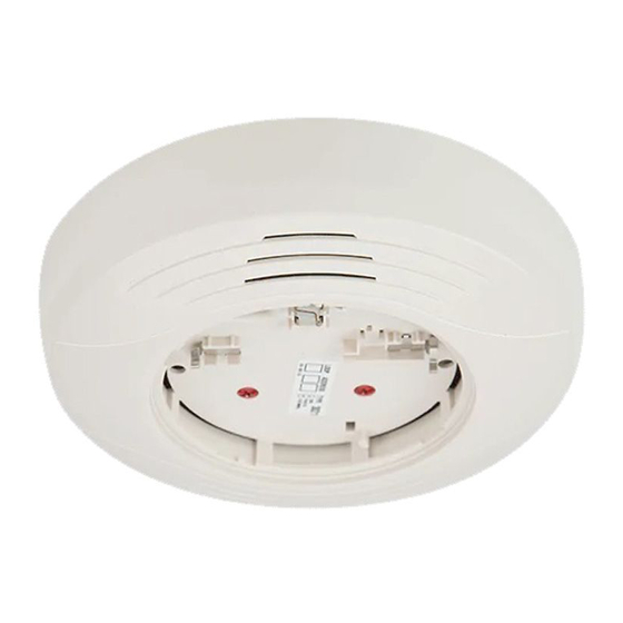
B224rB Plug-in
relay detector Base
SPeCifiCaTiOnS
Base Diameter:
Base Height (less sensor):
Operating Temperature Range:
Operating Humidity Range:
Electrical Ratings
Operating Voltage:
Standby Current:
Relay Characteristics
Coil:
Contact Type:
Contact Relay Ratings
CUrrenT raTing
2 A
3 A
2 A
0.46 A
0.7 A
0.3 A
0.9 A
0.5 A
0.3 A
0.24 A
0.25 A
Set Time (Position 1):
Set Time (Position 2):
Reset Time:
BefOre inSTaLLing
Please read the System Smoke Detector Applications Guide, which provides
detailed information on detector spacing, placement, zoning, wiring, and spe-
cial applications. Copies of this application guide are available from System
Sensor. NFPA 72 guidelines should be observed.
NOTICE: This manual should be left with the owner/user of this equipment.
IMPORTANT: The detector used with these bases must be tested and main-
tained regularly following NFPA 72 requirements. The detectors should be
cleaned at least once a year.
generaL infOrmaTiOn
The relay base is intended for use in an intelligent system. Form C latching
relay contacts are included for the control of an auxiliary function. The relay
can operate in two different modes (short and long delay). The activation time
when the short delay is used is 60 msec to 100 msec, while the activation time
for the long delay is 6 sec to 10 sec. A shunt with pin headers, located on the
base PC board, can be used to choose your desired delay. B224RB is set at
the short delay when manufactured. If you wish to use the long delay, please
move the shunt to the adjacent pair of pin headers. See Figures 2 and 6.
B224rB TerminaLS
nO. fUnCTiOn
1. Normal Close
2. Common
3. Normal Open
4. Comm. Line In (–) and Out (–)
5. Comm. Line In (+) and Out (+)
SS-450-003
6.85 in (17.4 cm)
1.61 in (4.1 cm)
Refer to applicable sensor Operating Temperature Range using the Base/Sensor Cross Reference Chart at systemsensor.com
10% to 93% Relative Humidity (Non-condensing)
15 to 32 VDC
170 µA
2 coil latching
Form C
maXimUm VOLTage
25 VAC
30 VDC
30 VDC
30 VDC
70.7 VAC
110 VDC
125 VDC
125 VAC
125 VAC
220 VDC
250 VAC
60 msec minimum, 100 msec maximum
6 seconds minimum, 10 seconds maximum
20 msec
firealarmresources.com
3825 Ohio Avenue, St. Charles, Illinois 60174
LOad deSCriPTiOn
General purpose (PF = 0.35)
General purpose
General purpose
(L/R = 20ms)
General purpose (PF = 0.35)
General purpose
General purpose
General purpose
General purpose (PF = 0.35)
General purpose
Resistive load
figUre 1. TerminaL deSignaTiOn:
5
Mount the mounting plate directly to an electrical box. The plate will mount
directly to 4-inch square (with and without plaster ring), 4-inch octagon, 3
½-inch octagon, single gang and double gang junction boxes.
1.
Connect field wiring to terminals, as shown in Figure 4.
2.
Attach the mounting plate to the junction box as shown in Figure 2.
3.
To mount the base, hook the tab on the base to the groove on the
mounting plate.
4.
Then, swing the base into position to engage the pins on the product
with the terminals on the mounting plate.
5.
Secure the base by tightening the mounting screws.
6.
Install a compatible smoke detector as described in the installation
manual for the detector.
1
1-800-SENSOR2, FAX: 630-377-6495
www.systemsensor.com
aPPLiCaTiOn
Non-coded
Non-coded
Coded
Non-coded
Non-coded
Non-coded
Non-coded
Non-coded
Non-coded
Non-coded
Non-coded
4
3
2
1
C0471-06
I56-3737-002R
Advertisement
Table of Contents

Related Manuals for System Sensor B224RB


Summary of Contents for System Sensor B224RB
- Page 1 60 msec to 100 msec, while the activation time for the long delay is 6 sec to 10 sec. A shunt with pin headers, located on the base PC board, can be used to choose your desired delay. B224RB is set at C0471-06 the short delay when manufactured.
- Page 2 inSTaLLaTiOn gUideLineS figUre 2. mOUnTing The BaSe TO an eLeCTriCaL BOX: All wiring must be installed in compliance with all applicable local codes and any special requirements of the local authority having jurisdiction, using the LOCATION OF RELAY proper wire sizes. The conductors used to connect smoke detectors to control ACTIVATION SHUNT - panels and accessory devices should be color-coded to reduce the likelihood MOVE TO SWITCH...
- Page 3 figUre 4. Wiring diagram: OTHER INTELLIGENT DEVICES SLC(+) SLC(–) (–) (–) Comm.(+) 5(+) 4(–) 2(Common) 3(NO) 1(NC) Comm.(–) 2 RELAY COMMON 1 NORMALLY CLOSED 3 NORMALLY OPEN CLASS A OPTIONAL WIRING C0890-01 figUre 5a. aCTiVaTing The TamPer-reSiST feaTUre: figUre 6: reLaY aCTiVaTiOn ShUnT: BREAK TAB AT USE SMALL-BLADED DOTTED LINE BY...
- Page 4 Please refer to insert for the Limitations of Fire Alarm Systems Three-Year LimiTed WarranTY System Sensor warrants its enclosed smoke detector base to be free from defects in ma- Department, RA #__________, 3825 Ohio Avenue, St. Charles, IL 60174. Please include terials and workmanship under normal use and service for a period of three years from a note describing the malfunction and suspected cause of failure.
Need help?
Do you have a question about the B224RB and is the answer not in the manual?
Questions and answers