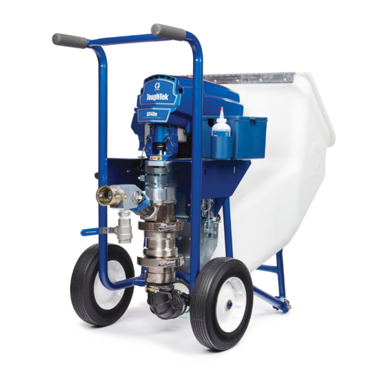
Graco ToughTek S340e Operation, Repair, And Parts
Portable stucco pump
Hide thumbs
Also See for ToughTek S340e:
- Operation, repair, and parts (38 pages) ,
- Instructions manual (34 pages) ,
- Operation, repair, and parts (38 pages)
Table of Contents
Advertisement
Quick Links
Operation, Repair, and Parts
ToughTek®
ToughTek® S340e
ToughTek®
S340e
S340e
Portable Stucco
Stucco Pump
Portable
Portable
Stucco
Electric
Electric sprayer
Electric
sprayer
sprayer for
for water
for
water- - - based
water
Systems
Systems (EIFS).
Systems
(EIFS).
(EIFS). For
For
For professional
professional use
professional
Not approved
approved for
for use
use in in in explosive
Not
Not
approved
for
use
Important
Important Safety
Important
Safety Instructions
Safety
Read all warnings and instructions in this manual and in related
manuals. Save
Save these
Save
these instructions.
these
For models and related manuals, see
page 3.
600 psi (4.13 MPa, 41.3 bar) Maximum
Fluid Working Pressure
All manuals and user guides at all-guides.com
Pump
Pump
based stucco
based
stucco
stucco base,
base, finish
base,
use
use only.
only.
only.
explosive atmospheres
atmospheres or or or hazardous
explosive
atmospheres
Instructions
Instructions
instructions.
instructions.
PROVEN QUALITY. LEADING TECHNOLOGY.
finish coat
finish
coat materials,
coat
materials, and
materials,
and Exterior
and
hazardous locations.
locations.
hazardous
locations.
3A3437F
Exterior Insulation
Exterior
Insulation and
Insulation
and Finish
and
EN
Finish
Finish
Advertisement
Table of Contents

Related Manuals for Graco ToughTek S340e


Summary of Contents for Graco ToughTek S340e
- Page 1 All manuals and user guides at all-guides.com Operation, Repair, and Parts ToughTek® ToughTek® ToughTek® S340e S340e S340e 3A3437F Portable Stucco Stucco Pump Pump Portable Portable Stucco Pump Electric Electric Electric sprayer sprayer sprayer for for water water- - - based water based stucco based...
-
Page 2: Table Of Contents
Spray..............18 Repair..............27 Prevent Pack-out ......... 18 Replace Pump Lower ........27 Before Starting or Stopping Material Parts..............30 Flow ..........18 Spraying............18 Technical Specifications........37 Spray Adjustments (Pole Spray Applicator) ... 19 Graco Standard Warranty........38 3A3437F... -
Page 3: Models
25A306† ✔ All 230V pumps include a Europe adapter and Australia adapter cord set. † Related Manuals Manuals Related Related Manuals Manuals are available at www.graco.com. Component manuals in English: Manual Description Manual Manual Description Description 3A3438 Pole Spray Applicator... -
Page 4: Replacement Parts And Accessories
All manuals and user guides at all-guides.com Replacement Parts and Accessories Replacement Replacement Replacement Parts Parts and Parts and Accessories Accessories Accessories Accessories Accessories Accessories 17G554 KIT, remote switch 17W604 KIT, remote switch, cable (switch and 100 ft cable) 17W829 KIT, remote switch, extension cord (110 ft) 248515 KIT, sponge ball, 30 mm for 25 mm (1.0 in.) dia. - Page 5 All manuals and user guides at all-guides.com Replacement Parts and Accessories Hopper Hopper Hopper 17J707 KIT, F340e, hopper with cover 17J709 KIT, F340e, hopper, bracket 17J812 KIT, F340e, stop, bracket 17J710 KIT, F340e, adjustable latch 17J708 KIT, F340e, stop, brackets Motor Motor Motor and...
-
Page 6: Warnings
All manuals and user guides at all-guides.com Warnings Warnings Warnings Warnings The following warnings are for the setup, use, grounding, maintenance, and repair of this equipment. The exclamation point symbol alerts you to a general warning and the hazard symbols refer to procedure-specific risks. - Page 7 All manuals and user guides at all-guides.com Warnings WARNING WARNING WARNING EQUIPMENT MISUSE MISUSE HAZARD HAZARD EQUIPMENT EQUIPMENT MISUSE HAZARD Misuse can cause death or serious injury. • Do not operate the unit when fatigued or under the influence of drugs or alcohol. •...
- Page 8 All manuals and user guides at all-guides.com Warnings WARNING WARNING WARNING SKIN INJECTION INJECTION HAZARD HAZARD SKIN SKIN INJECTION HAZARD High-pressure fluid from dispensing device, hose leaks, or ruptured components will pierce skin. This may look like just a cut, but it is a serious injury that can result in amputation. Get immediate immediate immediate surgical...
-
Page 9: Component Identification
All manuals and user guides at all-guides.com Component Identification Component Identification Identification Component Component Identification Overview Overview Overview Component Identification Identification Table Table Component Component Identification Table Key: Key: Key: Key: Key: Key: Electric Motor Hopper Pin Pump Lower Motor Power Switch Fluid Drain/Purge Valve Hopper Latch Remote Pump Control Switch (optional) -
Page 10: Motor Power Switch
All manuals and user guides at all-guides.com Component Identification Motor Power Power Switch Switch Connect Hoses Hoses and and Applicator Applicator Motor Motor Power Switch Connect Connect Hoses Applicator The motor power switch (S) must be in the ON for the •... -
Page 11: Install The Remote Switch (Optional)
All manuals and user guides at all-guides.com Component Identification Install the the Remote Remote Switch Switch (Optional) (Optional) Prime Prime with Prime with Material with Material Material Install Install Remote Switch (Optional) The remote switch is an additional accessory kit and does not come with models 25A300 and 25A304. -
Page 12: Grounding
All manuals and user guides at all-guides.com Grounding Grounding Grounding Grounding Extension Cords Cords Extension Extension Cords • Use only a 3-wire extension cord that has a grounding plug and a grounding receptacle that accepts the plug on the product. The equipment must be grounded to reduce the •... -
Page 13: Setup
All manuals and user guides at all-guides.com Setup Setup Setup Setup 5. Attach check valve (optional). Remove fluid outlet assembly (F). Attach check valve (M) to pump fluid outlet. Attach fluid outlet assembly to check valve (M) outlet. To avoid tipping over, ensure cart is on a flat and level surface. -
Page 14: Flush
All manuals and user guides at all-guides.com Flush Flush Flush Flush 3. Place applicator outlet in a waste container. The waste container must be large enough to hold all dispensed material. NOTICE NOTICE NOTICE Failure to flush prior to material curing in the system will result in damage to system and may require replacement of all system parts in contact with the material. - Page 15 All manuals and user guides at all-guides.com Flush 11. Circulate clean water: 14. Drain remaining water from system: a. Fill the system hopper with clean water. a. Place a drain pan beneath pump lower inlet connection. b. Turn the motor power switch (S) to ON to begin circulating water.
-
Page 16: Prime With Water
All manuals and user guides at all-guides.com Prime with Water Prime Prime Prime with with Water with Water Water 6. Run the clean-out ball(s) to coat the inside of the hoses. a. Remove the applicator from the end of the hose. -
Page 17: Mix The Material
All manuals and user guides at all-guides.com Mix the Material Mix the the Material Material Material Prime Prime with Prime with Material with Material Material Always follow the material manufacturer’s instructions for the material being sprayed. Material must be thoroughly mixed to a smooth consistency before loading it in the hopper. -
Page 18: Spray
All manuals and user guides at all-guides.com Spray Spray Spray Spray Prevent Pack Pack - - - out Prevent Prevent Pack 5. Turn the motor power switch (S) to ON. To avoid “packing out” the pump or hose: • Use the lowest pressure and largest nozzle size that provides an acceptable spray pattern. -
Page 19: Spray Adjustments (Pole Spray Applicator)
All manuals and user guides at all-guides.com Spray Adjustments (Pole Spray Applicator) Spray Adjustments Adjustments (Pole (Pole Spray Spray Applicator) Applicator) Spray Spray Adjustments (Pole Spray Applicator) 1. Test the spray pattern on cardboard. Hold the applicator 18 – 30 in. (45 – 76 cm) away from the surface. -
Page 20: Spray Adjustments (Htxtm Applicator)
All manuals and user guides at all-guides.com Spray Adjustments (HTXTM Applicator) Spray Adjustments Adjustments (HTX (HTX T T T M M M Applicator) Spray Spray Adjustments (HTX Applicator) Applicator) Air bleeds from the applicator nozzle whenever the air assist valve (DF) is open. Close the valve to stop the air flow if desired. -
Page 21: Fluid Drain/Purge Valve
All manuals and user guides at all-guides.com Fluid Drain/Purge Valve Fluid Fluid Fluid Drain/Purge Drain/Purge Valve Drain/Purge Valve Valve 1. Turn the flow adjustment knob (H) counterclockwise until it stops. 2. Turn the motor power switch (S) off. 3. Remove the applicator tip and the tip retainer. 4. -
Page 22: Hopper Removal
All manuals and user guides at all-guides.com Hopper Removal Hopper Hopper Hopper Removal Removal Removal NOTE: If the hopper elbow needs to be thoroughly NOTE: NOTE: cleaned, rotate knob (K) to loosen the clamp between the elbow and the hopper. Remove and clean the elbow. -
Page 23: Maintenance
All manuals and user guides at all-guides.com Maintenance Maintenance Maintenance Maintenance Daily Maintenance Maintenance Corrosion Protection Protection Daily Daily Maintenance Corrosion Corrosion Protection NOTICE NOTICE NOTICE To prevent rust, never leave water or water-based fluid in the pump overnight. NOTICE NOTICE NOTICE 1. -
Page 24: Troubleshooting
All manuals and user guides at all-guides.com Troubleshooting Troubleshooting Troubleshooting Troubleshooting 2. Check all possible problems, causes, and solutions listed below before disassembling pump. For troubleshooting and repair questions, please contact your distributor. 1. Perform Pressure Relief Procedure, page Mechanical/Fluid Mechanical/Fluid Mechanical/Fluid Flow Flow... -
Page 25: Electrical
All manuals and user guides at all-guides.com Troubleshooting Problem Problem Problem Cause Solution Cause Cause Solution Solution Material is too thick to push Hose is too restrictive Thin and mix material thoroughly to a lower through the hose without viscosity. packing out Use a pump system priming fluid (slime). - Page 26 All manuals and user guides at all-guides.com Troubleshooting Problem Problem Problem Cause Solution Cause Cause Solution Solution Control board status light blinks Connections above the motor may 1. Turn the motor power switch (S) to OFF and 15 times repeatedly are loose or damaged unplug the sprayer.
-
Page 27: Repair
All manuals and user guides at all-guides.com Repair Repair Repair Repair Replace Pump Pump Lower Lower Replace Replace Pump Lower Perform the procedure below to replace the entire pump lower with a new or different pump lower. 1. Perform the Pressure Relief Procedure, page 2. - Page 28 All manuals and user guides at all-guides.com Repair Replace Pump Pump Components Components Replace Replace Pump Components Remove the the pump pump lower lower (6a (6a – – – 17G864) 17G864) before before replacing replacing any any pump pump components. components.
- Page 29 All manuals and user guides at all-guides.com Repair Pump Components Components Parts Parts List List Pump Pump Components Parts List Ref. Part Description Qty. Ref. Part Description Qty. Ref. Ref. Part Part Description Description Qty. Qty. Ref. Ref. Part Part Description Description Qty.
-
Page 30: Parts
All manuals and user guides at all-guides.com Parts Parts Parts Parts S340e Systems Systems S340e S340e Systems 3A3437F... - Page 31 All manuals and user guides at all-guides.com Parts Ref. Part Part Description Qty. Ref. Part Part Description Qty. Ref. Ref. Part Description Description Qty. Qty. Ref. Ref. Part Description Description Qty. Qty. 2 2 2 17J707 HOPPER, 340e, 340e, with with 1 1 1 101566...
- Page 32 All manuals and user guides at all-guides.com Parts S340e Systems Systems (continued) (continued) S340e S340e Systems (continued) 3A3437F...
- Page 33 All manuals and user guides at all-guides.com Parts Ref. Part Description Qty. Ref. Part Description Qty. Ref. Ref. Part Part Description Description Qty. Qty. Ref. Ref. Part Part Description Description Qty. Qty. – – – – – – – – – – – – – – – 1 1 1 CART, CART, 340e,...
- Page 34 All manuals and user guides at all-guides.com Parts Driver Driver Driver and and Motor Motor Motor 3A3437F...
- Page 35 All manuals and user guides at all-guides.com Parts Ref. Part Description Qty. Ref. Part Description Qty. Ref. Ref. Part Part Description Description Qty. Qty. Ref. Ref. Part Part Description Description Qty. Qty. – – – – – – – – – – – – – – – MOTOR, electric electric 1 1 1...
- Page 36 All manuals and user guides at all-guides.com Parts Control Box Control Control Ref. Ref. Ref. Part Part Part Description Description Description Qty. Qty. Qty. Ref. Ref. Ref. Part Part Part Description Description Description Qty. Qty. Qty. – – – – – – – – – – – – – – – –...
-
Page 37: Technical Specifications
All manuals and user guides at all-guides.com Technical Specifications Technical Specifications Specifications Technical Technical Specifications ToughTek ToughTek ToughTek S340e S340e Sprayer S340e Sprayer Sprayer U.S. Metric Metric Metric U.S. U.S. Maximum Fluid Working Pressure 600 psi 4.1 MPa, 41 Bar Stroke Length 2.25 in. -
Page 38: Graco Standard Warranty
With the exception of any special, extended, or limited warranty published by Graco, Graco will, for a period of twelve months from the date of sale, repair or replace any part of the equipment determined by Graco to be defective. This warranty applies only when the equipment is installed, operated and maintained in accordance with Graco’s written recommendations.
Need help?
Do you have a question about the ToughTek S340e and is the answer not in the manual?
Questions and answers