Graco ToughTek S340e Instructions Manual
Portable self-leveling underlayment pump
Hide thumbs
Also See for ToughTek S340e:
- Operation, repair, and parts (38 pages) ,
- Operation, repair, and parts (38 pages) ,
- Operation, repair, and parts (38 pages)
Table of Contents
Advertisement
Quick Links
Instructions
ToughTek
Self-Leveling Underlayment Pump
Electric sprayer for water-based cementitious underlayment material.
For professional use only.
Not approved for use in explosive atmospheres or hazardous locations.
600 psi (4.13 MPa, 41.3 bar)
Maximum Fluid Working Pressure
See page 2 for model information and approvals.
Important Safety Instructions
Read all warnings and instructions in this
manual before using the equipment.
Save these instructions.
®
SL340e Portable
3A7829A
EN
Advertisement
Table of Contents

Related Manuals for Graco ToughTek S340e


Summary of Contents for Graco ToughTek S340e
- Page 1 Instructions ® ToughTek SL340e Portable 3A7829A Self-Leveling Underlayment Pump Electric sprayer for water-based cementitious underlayment material. For professional use only. Not approved for use in explosive atmospheres or hazardous locations. 600 psi (4.13 MPa, 41.3 bar) Maximum Fluid Working Pressure See page 2 for model information and approvals.
-
Page 2: Table Of Contents
Clearing a Clogged Hose ....14 Graco Standard Warranty ....34 Shutdown . -
Page 3: Warnings
Warnings Warnings The following warnings are for the setup, use, grounding, maintenance, and repair of this equipment. The exclamation point symbol alerts you to a general warning and the hazard symbols refer to procedure-specific risks. When these symbols appear in the body of this manual or on warning labels, refer back to these Warnings. Product-specific hazard symbols and warnings not covered in this section may appear throughout the body of this manual where applicable. - Page 4 Warnings WARNING SKIN INJECTION HAZARD High-pressure fluid from applicator, hose leaks, or ruptured components will pierce skin. This may look like just a cut, but it is a serious injury that can result in amputation. Get immediate surgical treatment. • Do not point applicator at anyone or at any part of the body.
- Page 5 Warnings WARNING PRESSURIZED ALUMINUM PARTS HAZARD Use of fluids that are incompatible with aluminum in pressurized equipment can cause serious chemical reaction and equipment rupture. Failure to follow this warning can result in death, serious injury, or property damage. • Do not use 1,1,1-trichloroethane, methylene chloride, other halogenated hydrocarbon solvents or fluids containing such solvents.
-
Page 6: Component Identification
Component Identification Component Identification Overview Ref. Description Ref. Description Over-Center Latch Electric Motor Control Board Status Light Pump Lower Hopper Clamp Fluid Drain/Purge Valve Motor Power Switch Fluid Outlet Inlet Latch Flow Adjustment Knob Hopper 3A7829A... -
Page 7: Fluid Drain/Purge Valve
Component Identification Fluid Drain/Purge Valve Motor Power Switch The motor power switch (S) must be in the ON position for the sprayer to pump material. To avoid injury from splashing fluid, never open a cam-lock hose or applicator fitting while there is pressure in the fluid line. -
Page 8: Grounding
Grounding Grounding Extension Cords • Use only a 3-wire extension cord that has a grounding plug and a grounding receptacle that The equipment must be grounded to reduce the risk accepts the plug on the product. of static sparking and electric shock. Electric or static sparking can cause fumes to ignite or explode. -
Page 9: Operation
Operation Operation 4. Attach hose to applicator fluid inlet and pump fluid Setup outlet (F), then secure Velcro straps (V) around the cam lock fitting. To avoid tipping over, make sure the cart is on a flat and level surface. Failure to do so could result in injury or equipment damage. -
Page 10: Flush
Operation 1. Follow the Pressure Relief Procedure on page 14. Flush 2. Place the hose outlet in a waste container. The waste container must be large enough to hold all dispensed material. NOTICE Failure to flush prior to material curing in the system will result in damage to system and may require replacement of all system parts in contact with the material. - Page 11 Operation 9. Circulate clean water: c. Reattach the hose to the pump outlet and turn the motor power switch (S) to ON to resume a. Fill the system hopper with clean water. flushing the hose. b. Use a scrub brush to scrub the walls of the d.
-
Page 12: Mix The Material
Operation Always push out any remaining water into a waste Mix the Material container before circulating material. Always circulate clean material back into the hopper for a few minutes Always follow the material manufacturer’s instructions before beginning to pour. for the material being sprayed. Material must be thoroughly mixed to a smooth consistency before 1. -
Page 13: Pouring
Operation 3. Turn the motor power switch (S) to ON. Pouring Prevent Pack-out To avoid “packing out” the pump or hose: • Use the lowest pressure and largest nozzle size that provides an acceptable flow rate. This will also result in seals and wear parts lasting much longer. •... -
Page 14: Pressure Relief Procedure
Operation 4. If the ball valve kit (17J703) has been installed, Pressure Relief Procedure open the ball valve. Follow the Pressure Relief Procedure 5. If you suspect the hose is completely clogged, or whenever you see this symbol. that pressure has not been fully relieved after following the previous steps, slowly open the fluid drain/purge valve (C) at the pump outlet and drain material into a waste pail. -
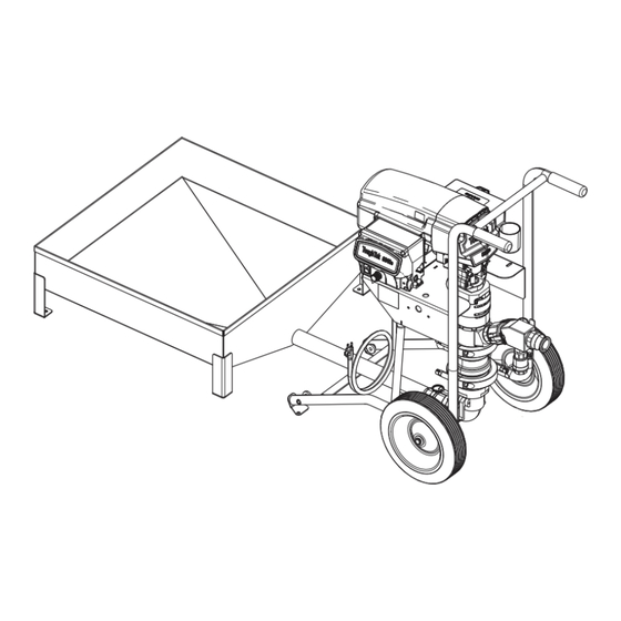
Page 15: Shutdown
Operation Shutdown Lifting Instructions When lifting the unit, only lift at the points indicated by the arrows shown in the illustration. Never lift with the hopper attached. To avoid injury from splashing fluid, never open a cam-lock hose or applicator fitting while there is pressure in the fluid line. -
Page 16: Maintenance
Operation Maintenance Preventative Maintenance The operating conditions of your particular system determine how often maintenance is required. Establish a preventative maintenance schedule by recording when and what kind of maintenance is needed, and then determine a regular schedule for checking your 1. -
Page 17: Troubleshooting
Troubleshooting Troubleshooting 2. Check all possible problems, causes, and solutions listed below before disassembling the pump. NOTE: For troubleshooting and repair questions, contact your distributor. 1. Follow the Pressure Relief Procedure on page 14. Mechanical/Fluid Flow Problem Cause Solution The displacement pump The piston ball check is not seating Service the piston ball check. - Page 18 Troubleshooting Problem Cause Solution Speed is erratic and/or The material supply has been Refill the hopper and prime the pump. accelerated. exhausted, or clogged the suction. The piston valve or packings are Clear the piston valve and replace the worn or open. packings.
-
Page 19: Electrical
Troubleshooting Electrical Problem Cause Solution The control board status light blinks The control board is detecting Check voltage supply to the sprayer: four times repeatedly. multiple voltage surges. 1. Turn the motor power switch (S) to OFF and unplug the sprayer. 2. - Page 20 Troubleshooting Problem Cause Solution The control board status light blinks Connections above the motor may be 1. Set the motor power switch (S) to 15 times repeatedly. loose or damaged. OFF and unplug the sprayer. 2. Remove the motor shroud. 3.
-
Page 21: Repair
Repair Repair Perform the procedure below to replace the entire pump lower with a new or different pump lower. 1. Follow the Pressure Relief Procedure on page 14. 2. Disconnect the hopper, material hose, and power. NOTE: When reinstalling the pump lower, the jam 3. -
Page 22: Replace Pump Components
Repair Replace Pump Components Remove the pump lower (6a - 257295) before replacing any pump components. For a list of available pump lower kits, see the list on the following page. Apply grease lubricant to all o-rings and seals. NOTE: 3A7829A... - Page 23 Repair Pump Components Parts List Ref. Part Description Qty. Ref. Part Description Qty. 17G226 HOUSING, inlet, ball guide 17G220 HOUSING, outlet 16V143 HOUSING, inlet 17G859 NUT, jam, black † SEA, carbide, valve, inlet 17G865 KIT, bearing, seal throat, † O-RING, 50 mm x 2.5 mm 3-pack 15H833†...
-
Page 24: Parts
Parts Parts SL340e SL340e Parts List Ref. Part Description Qty. Ref. Part Description Qty. 18B767 HOSE, EPDM, 2.0 in. 195551 RETAINER, plug, adapter 18B766 CLAMP, over center, 2.0 in. 242005 CORD SET, adapter, Australia 513550 COUPLER, hose shank 242001 CORD SET, adapter, Europe 16V510 FITTING, cam and groove, 18B709 HOPPER, assy, SL340 elbow, 2.0 in. - Page 25 Parts SL340e (continued) Apply lubricant grease to threads. Apply pipe sealant to threads. Torque to 40 - 45 in-lb (4.5 - 5.0 N•m). Torque to 25 +/- 5 ft-lb (33.8 +/- 6.7 N•m). 3A7829A...
- Page 26 Parts SL340e Parts List (continued) Ref. Part Description Qty. Ref. Part Description Qty. † SHIELD, motor, painted - - - - - CART, 340e, painted 106115 WASHER, lock (hi collar) † MODULE, 340e, motor control, 114666 SCREW, cap, socket head 120V - - - - - PLUG, tube...
-
Page 27: Control Box
Parts Control Box Torque to 10 - 15 in-lb (1.1 - 1.7 N•m). Torque to 30 - 35 in-lb (3.3 - 3.9 N•m). Driver and Motor Parts List Ref. Part Description Qty. Ref. Part Description Qty. 16Y786 LABEL, control, elec, std - - - - - CONTROL, board, 50 amp 217... -
Page 28: Driver And Motor
Parts Driver and Motor Torque to 190 - 210 in-lb (21.4 - 23.7 N•m). Apply lubricant to all gear teeth proportionally. Copper colored washer. Steel colored washer. 3A7829A... - Page 29 Parts Driver and Motor Parts List Ref. Part Description Qty. Ref. Part Description Qty. 119778 SPRING, retaining - - - - - MOTOR, electric 15† - - - - - COVER, front, plastic, painted - - - - - GEAR, combination 16†...
-
Page 30: Replacement Parts And Accessories
Replacement Parts and Accessories Replacement Parts and Accessories Accessories 17G554 Kit, remote switch, 340e 17W829 Kit, remote switch, extension cord (100 ft) 114271 Strap, retaining 240296 Kit, retaining straps, 4-pack 17W604 Kit, remote switch, cable (switch and 100 ft cable) 17J703 Kit, applicator, ball valve (applicator) Kit, clean out, sponge ball, 1.18 in. -
Page 31: Dimensions
Dimensions Dimensions Ref. Dimension 23.05 in. (57 cm) 39.4 in. (100 cm) 35.0 in. (89 cm) 66.0 in. (168 cm) 10.25 in. (26 cm) 3A7829A... -
Page 32: Recycling And Disposal
Recycling and Disposal Recycling and Disposal End of Product Life At the end of a product’s useful life, recycle it in a responsible manner. California Proposition 65 CALIFORNIA RESIDENTS WARNING: Cancer and reproductive harm – www.P65warnings.ca.gov. 3A7829A... -
Page 33: Technical Specifications
Technical Specifications Technical Specifications ToughTek SL340e Metric Maximum Fluid Working Pressure 600 psi 4.1 MPa, 41 Bar Stroke Length 2.25 in. 57 mm Maximum pump speed (Do not exceed 150 cycles per minute maximum recommended speed of fluid pump to prevent premature pump wear) Weight (dry with hopper) 205 lb 93 kg... -
Page 34: Graco Standard Warranty
With the exception of any special, extended, or limited warranty published by Graco, Graco will, for a period of twelve months from the date of sale, repair or replace any part of the equipment determined by Graco to be defective.
Need help?
Do you have a question about the ToughTek S340e and is the answer not in the manual?
Questions and answers