Table of Contents
Advertisement
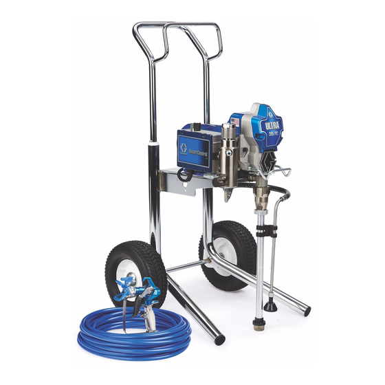
Operation, Parts
Electric Airless
Sprayers
For professional use only.
Not approved for use in explosive atmospheres or hazardous locations.
For portable airless spraying of architectural paints and coatings.
Ultra 395 PC, Ultimate NOVA 395 PC, Classic S 395 PC,
Classic S 495 PC, Ultra 395 PC Pro
3300 psi (228 bar, 22.8 MPa) Maximum Working Pressure
Ultra 395 PC Classic, Ultra 495 PC Classic
3000 psi (207 bar, 20.7 MPa) Maximum Working Pressure
See page 3 for additional model information.
Important Safety Instructions
Read all warnings and instructions in this manual and related manuals. Be familiar with
the controls and the proper usage of the equipment. Save these instructions.
Gun– 311861 (Contractor/FTx) 312830 (SG3)
Use only genuine Graco replacement parts.
The use of non-Graco replacement parts may void warranty.
Related Manuals
Pump – 334599
334466F
EN
ti24762a
Advertisement
Table of Contents

Related Manuals for Graco Classic S 395 PC


Summary of Contents for Graco Classic S 395 PC
-
Page 1: Important Safety Instructions
Not approved for use in explosive atmospheres or hazardous locations. For portable airless spraying of architectural paints and coatings. Ultra 395 PC, Ultimate NOVA 395 PC, Classic S 395 PC, Classic S 495 PC, Ultra 395 PC Pro 3300 psi (228 bar, 22.8 MPa) Maximum Working Pressure Ultra 395 PC Classic, Ultra 495 PC Classic 3000 psi (207 bar, 20.7 MPa) Maximum Working Pressure... -
Page 2: Table Of Contents
Graco Standard Warranty ........ -
Page 3: Models
Models Models Hi-Boy Lo-Boy Stand Model Ultra 395 PC 17C314 17C315 17C317 110474 Ultimate NOVA 826196 826197 826198 Certified to 395 PC CAN/CSA C22.2 No. 68 Conforms to UL 1450 Ultra 395 PC 17C391 Japan/Taiwan Classic S 395 PC 17C361 17C362 CEE 7/7 Classic S 495 PC... -
Page 4: Warnings
Warnings Warnings The following warnings are for the setup, use, grounding, maintenance, and repair of this equipment. The exclamation point symbol alerts you to a general warning and the hazard symbols refer to procedure-specific risks. When these symbols appear in the body of this manual or on warning labels, refer back to these Warnings. -
Page 5: Fire And Explosion Hazard
Use Graco conductive or grounded high-pressure airless paint sprayer hoses. •... - Page 6 • Check hoses and parts for signs of damage. Replace any damaged hoses or parts. • This system is capable of producing 3300 psi. Use Graco replacement parts or accessories that are rated a minimum of 3300 psi. • Always engage the trigger lock when not spraying. Verify the trigger lock is functioning properly.
- Page 7 Warnings ELECTRIC SHOCK HAZARD This equipment must be grounded. Improper grounding, setup, or usage of the system can cause electric shock. • Turn off and disconnect power cord before servicing equipment. • Connect only to grounded electrical outlets. • Use only 3-wire extension cords. •...
-
Page 8: Component Identification
Component Identification Component Identification Stand Models ti24761a Fluid Intake ON/OFF Switch Pump Pressure Control Fluid Outlet Prime Valve Power Cord Wrap Tip Guard Filter Spray Tip Finger Guard / TSL Fill Point Model/Serial Tag (Not shown, located Airless Hose on bottom of unit.) Power Cord Trigger Lock M Drain Tube... -
Page 9: Lo-Boy Models
Component Identification Lo-Boy Models ti24835a Trigger Lock ON/OFF Switch M Drain Tube Pressure Control Fluid Intake Prime Valve Pump Tip Guard Fluid Outlet Spray Tip Filter Finger Guard / TSL Fill Point Airless Hose Model/Serial Tag (Not shown, located Power Cord on bottom of unit.) 334466F... -
Page 10: Hi-Boy Models
Component Identification Hi-Boy Models ti24837a 334466F... - Page 11 Component Identification Hi-Boy Models M Drain Tube ON/OFF Switch Fluid Intake Pressure Control Pump Prime Valve Fluid Outlet Tip Guard Hanger Spray Tip Filter Finger Guard / TSL Fill Point Airless Hose Pail Hook Power Cord Model/Serial Tag (Not shown, located Trigger Lock on bottom of unit.) 334466F...
-
Page 12: Grounding
Grounding Grounding The equipment must be grounded to reduce the risk of static sparking and electric shock. An electric or static spark can cause fumes to ignite or explode. An improper ground can cause electric shock. A good ground provides an escape wire for the electric current. -
Page 13: Pressure Relief Procedure
Pressure Relief Procedure Pressure Relief Procedure Engage the trigger lock. Follow the Pressure Relief Procedure whenever you see this symbol. This equipment stays pressurized until pressure is manually relieved. To help prevent serious injury from pressurized ti24931a fluid, such as skin injection, splashed fluid Turn pressure control to lowest setting. -
Page 14: Trigger Lock
Pressure Relief Procedure Trigger Lock Turn the prime valve down. Put drain tube in a pail. Leave prime valve in the down (drain) position until you are ready Always engage the trigger lock when sprayer to spray again. is stopped to prevent the gun from being triggered accidentally by hand or if dropped or bumped. -
Page 15: Setup
When unpacking sprayer for the first time or after long term storage perform setup procedure. When first setup is performed remove shipping plug from fluid outlet. Connect Graco airless hose to fluid outlet. Use wrenches to tighten securely. ti24633a Use wrenches to tighten securely. - Page 16 Setup Remove tip guard. Squeeze bottle to dispense enough TSL to fill the space between the pump rod and packing nut seal. ti24592a When unpacking sprayer for the first ti24639a time remove packaging materials from inlet strainer. After long term storage Make certain ON/OFF switch is OFF.
- Page 17 Setup 15. Turn prime valve horizontal. Disengage trigger lock. ti24608a 11. Place fluid intake with drain tube in grounded metal pail partially filled with flushing fluid. See Grounding, page 12. ti24646a NOTE: New sprayers are shipped with 16. Hold a metal part of the gun firmly to a storage fluid that must be flushed out with grounded metal pail.
-
Page 18: Startup
Startup Startup Perform Pressure Relief Procedure, page 13. Turn pressure control to lowest pressure. ti24645b Turn prime valve horizontal. Disengage trigger lock. ti24603b Turn ON/OFF switch to ON position. ti24644a Place fluid intake in paint pail. Place drain tube in waste pail. Increase pressure 1/2 turn to start motor. - Page 19 Startup High-pressure spray is able to inject toxins into the body and cause serious bodily injury. Do not stop leaks with hand or rag. Inspect for leaks. If leaks occur, perform Pressure Relief Procedure, page 13, then tighten all fittings and repeat Startup procedure.
-
Page 20: Operation
Operation Operation Spray Tip Installation 3. Screw assembly onto gun. Tighten. 1. Perform Pressure Relief Procedure, page 13. 2. Use spray tip (A) to insert ™ OneSeal (B) into tip guard (C). ti24652a Spray When a RAC X™ FF LP Fine Finish Low Pressure reversible spray tip is used, spraying pressure can be lowered. -
Page 21: Clear Tip Clog
Operation Spray test pattern. Adjust pressure to Release trigger. Engage trigger lock. eliminate heavy edges. Rotate Spray Tip. Disengage trigger lock. Trigger gun at waste area to clear clog. ti24669a Use smaller tip size if pressure adjustment cannot eliminate heavy edges. -
Page 22: Digital Display
Operation Digital Display Press and hold display button to change pressure units (psi, bar, or MPa). Some models are equipped with a digital display. This section explains how to use this feature. Pressure Display 1. Perform Pressure Relief Procedure, page 13. ti2888a Plug sprayer into grounded outlet. - Page 23 Operation Sprayer model number is displayed To erase last error code, press and hold followed by Data Point 1 which is the unit display button. power on time in hours. Press display button again to display Data Point 4. The software revision is displayed.
-
Page 24: Cleanup
Operation Cleanup Perform Pressure Relief Procedure, page 13. Remove tip guard and Spray Tip. For additional information, see separate gun manual. ti24709a Place fluid intake in flushing fluid. Use water for water base paint and mineral spirits for oil-based paint. Place drain tube in waste pail. - Page 25 Operation Turn prime valve horizontal. Increase pressure 1/2 turn to start motor. Hold gun against paint pail. Disengage trigger lock. Trigger gun and increase pressure until the pump runs steady and flushing fluid appears. ti24713a Raise fluid intake above flushing fluid. ti24712a Stop triggering gun.
- Page 26 Operation 10. Turn prime valve horizontal. Trigger gun 13. Remove filter from gun and sprayer if into flushing pail to purge fluid from hose. installed. Clean and inspect. Install filter. See separate gun manual. 11. Engage trigger lock. 20 s ti24718a 14.
-
Page 27: Maintenance
Maintenance Maintenance Routine maintenance is important to ensure proper operation of your sprayer. Maintenance includes performing routine actions which keep your sprayer in operation and prevents trouble in the future. Activity Interval Inspect/clean sprayer filter, fluid inlet strainer, and gun Daily or each time you spray filter. -
Page 28: Troubleshooting
Troubleshooting Troubleshooting Mechanical/Fluid Flow Follow Pressure Relief Procedure, Check all possible problems and causes page 13, before checking or repairing. before disassembling the unit. What to Check What to Do If check is OK, go to next When check is not OK, Problem check refer to this column... - Page 29 Troubleshooting What to Check What to Do If check is OK, go to next When check is not OK, Problem check refer to this column Pump output is low Pump rod damage. Repair pump. See pump manual. Low stall pressure. Turn pressure knob fully clockwise.
- Page 30 Troubleshooting What to Check What to Do If check is OK, go to next When check is not OK, Problem check refer to this column Fluid is spitting from gun Air in pump or hose. Check and tighten all fluid connections.
-
Page 31: Electrical
Troubleshooting Electrical View digital display or remove control box cover to view control board status light. To determine which code (or any Symptom: Sprayer does not run, stops other code besides voltage supply) refer running, or will not shut off. to the control board status light. - Page 32 Troubleshooting Problem What to Check How to check Check transducer or transducer Sprayer does not run at all Make sure there is no pressure in the system (see Pressure Relief connections Procedure, page 13). Check fluid Display shows E=02 path for clogs, such as clogged filter. Use airless paint spray hose with no metal braid.
- Page 33 Troubleshooting Problem What to Check How to check Sprayer does not run at all Check voltage supply to the sprayer Turn ON/OFF switch OFF and (control board is detecting a multiple disconnect power to sprayer. voltage surges). Locate a good voltage supply to Display shows E=04 prevent damage to electronics.
- Page 34 Troubleshooting Problem What to Check How to check 6.Connect the Red and Black leads from the motor to an Ohm meter. Rotate the motor while checking for opens. If an open is found replace the motor. BLACK (-) RED (+) YELLOW 1-3 ohms ti24723a...
- Page 35 Troubleshooting Problem What to Check How to check 8.Use an Ohm meter to check motor for shorts. Connect (–) meter lead to motor case. Move the (+) meter lead to each motor wire. Meter should read open on all wires. GROUND BLACK YELLOW...
- Page 36 Troubleshooting Problem What to Check How to check Basic electrical problems Motor leads are securely fastened Replace loose terminals; crimp to and properly mated leads. Be sure terminal are firmly connected. Clean circuit board terminals. Securely reconnect leads. For loose motor brush lead Tighten terminal screws.
- Page 37 Troubleshooting Sprayer Will Not Run (See following page for steps) Sprayer Will Not Run (see following pages for steps) Remove Control box cover. Turn sprayer ON. Observe control board status light on See Step 1. Do you control board (see page 27). have over 100 VAC (220 VAC for 230v units)? No Light...
- Page 38 Troubleshooting Step 1: Step 3: Plug Power cord in and turn Check motor thermal switch. switch ON. Connect probes Unplug yellow wires. Meter to L and N on control board. should read continuity. Turn meter to AC Volts. NOTE: Motor should be cool during reading.
- Page 39 Troubleshooting Sprayer Will Not Shut Off Remove control box cover so the control board status light can be viewed Perform Pressure Relief Procedure, if available. page 13. Leave prime valve open (down) and turn ON/OFF switch OFF. Troubleshooting Procedure Plumb pressure gauge into paint hose, Mechanical problem: plug sprayer in, and turn power switch ON.
-
Page 40: Stand Sprayers
Stand Sprayers Stand Sprayers Models 17C314, 17C359, 17C361, 17C390, 17C391, 17C392, 17C409, 17E023, 17E024, 826196 Ref. Torque 140-160 in-lb (15.8 - 18.1 N•m) 30-35 in-lb (3.4 - 4.0 N•m) See page 50. ti24754a 334466F... - Page 41 Stand Sprayers Models 17C314, 17C359, 17C361, 17C390, 17C391, 17C392, 17C409, 17E023, 17E024, 826196 Ref. Torque 140-160 in-lb (15.8 - 18.1 N•m) 30-35 in-lb (3.4 - 4.0 N•m) Hammer tight 25-30 ft-lb (33.9 - 40.7 N•m) ti24753a 334466F...
-
Page 42: Stand Sprayers Parts List
Stand Sprayers Stand Sprayers Parts List Models 17C314, 17C359, 17C361, 17C390, 17C391, 17C392, 17C409, 17E023, 17E024, 826196 Ref. Part Description Qty. Ref. Part Description Qty. MOTOR, includes 54a, 117501 SCREW, mach, hex washer hd 287015 110V / 120V 17C539 COVER, front, painted 287060 230V 15B465... -
Page 43: 395 Lo-Boy Sprayers
395 Lo-Boy Sprayers 395 Lo-Boy Sprayers Models 17C315, 826197 Ref. Torque 140-160 in-lb (15.8 - 18.1 N•m) 30-35 in-lb (3.4 - 4.0 N•m) See page 50. ti24829a 334466F... - Page 44 395 Lo-Boy Sprayers Models 17C315, 826197 Ref. Torque 140-160 in-lb (15.8 - 18 30-35 in-lb (3.4 - 4.0 N•m Hammer tight 25-30 ft-lb (33.9 - 40.7 N ti24826a 334466F...
-
Page 45: 395 Lo-Boy Sprayers Parts List
395 Lo-Boy Sprayers 395 Lo-Boy Sprayers Parts List Models 17C315, 826197 Ref. Part Description Qty. Ref. Part Description Qty. 54b 248189 FAN, motor, includes 117501 SCREW, mach, hex washer hd 246381 HOSE, drain, stand, 117559 O-ring includes 39,62 17C539 COVER, front, painted 246385 STRAINER, 7/8-14 unf 15B465... -
Page 46: Hi-Boy Sprayers
Hi-Boy Sprayers Hi-Boy Sprayers Models 17C317, 17C362, 17C408, 17E025, 17E026, 826198 Ref. Torque 140-160 in-lb (15.8 - 18.1 N•m) 30-35 in-lb (3.4 - 4.0 N•m) 23-27 in-lb (2.6 - 3.1 N•m) See page 50. ti24834b 334466F... - Page 47 Hi-Boy Sprayers Models 17C317, 17C362, 17C408, 17E025, 17E026, 826198 Ref. Torque 140-160 in-lb (15.8 - 18.1 N•m) 30-35 in-lb (3.4 - 4.0 N•m) Hammer tight 25-30 ft-lb (33.8 - 40.6 N•m) ti24830a 334466F...
-
Page 48: Hi-Boy Sprayers Parts List
Hi-Boy Sprayers Hi-Boy Sprayers Parts List Models 17C317, 17C362, 17C408, 17E025, 17E026, 826198 Ref. Part Description Qty. Ref. Part Description Qty. 287952 HOSE, drain, includes 117501 SCREW, mach, hex washer hd 246385 STRAINER, 7/8-14 unf 103413 O-ring 17C485 FRAME, cart, hi 17C539 COVER, front, painted 17C992... -
Page 49: Accessories And Labels
Accessories and Labels Accessories and Labels Ref. 34 Card, Ref. 63 Ref. 65 Ref. 46 Ref. 53 Ref. 61 Medical Label, Label, Sprayer Hose, 1/4 Ref. 52 Label, Gun, Alert Danger Warning Model in. x 50 ft Label, Front Side Spray... -
Page 50: Control Box
Control Box Control Box Ref. Torque 140-160 in-lb (15.8 - 18.1 N•m) 30-35 in-lb (3.4 - 4.0 N•m) 20-25 in-lb (2.3 - 2.8 N•m) 37-43 ft-lb (50.2 - 58.3 N•m) 130-150 in-lb (14.7 - 16.9 N•m) ti24755b 334466F... -
Page 51: Control Box Parts List
Control Box Control Box Parts List Ref. Part Description Qty. Ref. Part Description Qty. CONTROL, board 117828 PACKING, o-ring 246378 110V, UK 111457 PACKING, o-ring 246379 120V, US/Japan 111600 PIN, grooved 246380 230V, 277364 GASKET, seat, valve Europe/Asia/ANZ 115494 SCREW, mach, 24X292 230V, China Phillips, pan hd... -
Page 52: Wiring Diagrams
Wiring Diagrams Wiring Diagrams 110/120V Black ON/OFF Black Switch Power Plug Black White Green Red (+) Black (-) from Motor ti2471a 2 x White 334466F... -
Page 53: 230V
Wiring Diagrams 230V NOTICE Heat from inductor coil of filter board may destroy wire insulation that comes in contact with it. Exposed wires could cause shorts and component damage. Bundle and tie loose wires so none lay in contact with inductor coil on the filter board. Black ON/OFF Switch... -
Page 54: Technical Specifications
Technical Specifications Technical Specifications Ultra 395/495 PC Classic, Ultra 395 PC, Ultimate NOVA 395 PC, Classic S 395/495 PC, Ultra 395 PC Pro Metric Sprayer Maximum fluid working pressure Ultra 395/495 PC Classic 3000 psi 207 bar, 20.7 MPa Ultra 395 PC, Ultimate NOVA... - Page 55 Technical Specifications Ultra 395/495 PC Classic, Ultra 395 PC, Ultimate NOVA 395 PC, Classic S 395/495 PC, Ultra 395 PC Pro Metric @ 70 psi (0.48 MPa, 4.8 bar) Noise** (dBa) Sound pressure 90 dBa Sound power 100 dBa Materials of Construction...
-
Page 56: Graco Standard Warranty
Graco’s written recommendations. This warranty does not cover, and Graco shall not be liable for general wear and tear, or any malfunction, damage or wear caused by faulty installation, misapplication, abrasion, corrosion, inadequate or improper maintenance, negligence, accident, tampering, or substitution of non-Graco component parts. -
Page 57: Graco Information
For the latest information about Graco products, visit www.graco.com. For patent information, see www.graco.com/patents. TO PLACE AN ORDER, contact your Graco distributor or call 1-800-690-2894 to identify the nearest distributor. All written and visual data contained in this document reflects the latest product information available at the time of publication.
Need help?
Do you have a question about the Classic S 395 PC and is the answer not in the manual?
Questions and answers