Table of Contents
Advertisement
Quick Links
Advertisement
Table of Contents

Related Manuals for Sapphire Audio IPC-FP6


Summary of Contents for Sapphire Audio IPC-FP6
- Page 1 User’s Manual AMD V2000 Mini-ITX Board IPC-FP6 TRADEMARK All products and company names are trademarks or registered trademarks of their respective holders. These specifications are subject to change without notice. Manual Revision 1.0 September 24, 2021...
- Page 2 Federal Communications Commission (FCC) Statement This device has been tested and found to comply with the limits for a Class B digital device, pursuant to Part 15 of FCC Rules. These limits are designed to provide reasonable protection against harmful interference in a residential installation.
- Page 3 Waste Electrical and Electronic Equipment (WEEE) Statement To protect the global environment, this product must be sent to separate collection facilities for recovery and recycling. DISPOSAL Do not dispose of this product as unsorted municipal waste. Collect such waste separately for special treatment. Manufacturer Sapphire Technology Limited Unit 1909-1919, 19/F., Tower 2 Grand Central Plaza...
-
Page 4: Table Of Contents
Table of Contents Chapter 1 Introduction ................1 1-1 Mainboard Specifications ..............1 1-2 Mainboard Layout ................4 I/O Back Panel ................7 1-3 Mainboard Dimension ..............11 Chapter 2 Installation ................13 2-1 Installing System Memory ............. 13 Memory Configuration ..............13 Memory Installation ............... - Page 5 2-4 System LED Status Indicators ............24 Chapter 3 Configuring the BIOS .............. 25 3-1 Select Boot Device ............... 25 3-2 Enter BIOS Setup ................. 25 3-3 Main Menu ..................27 3-4 Advanced Menu ................28 Trusted Computing ................ 28 ACPI Settings ................
-
Page 6: Chapter 1 Introduction
Chapter 1 Introduction 1-1 Mainboard Specifications ® AMD V2000 series APU for FP6 package with Zen 2 core Graphics ® AMD Radeon series graphics Supports four independent displays with DisplayPort and one eDP connector shared with DP1 DisplayPort Port Supported resolution DisplayPort 1.4 / eDP 1.3... - Page 7 Supports AHCI (Advanced Host Controller Interface) Onboard LAN ® One Gigabit Ethernet from Realtek RTL8111H Gigabit controller ® One 10 Gigabit Ethernet from Marvell AQC107 Gigabit controller Onboard TPM Supports TPM2.0 from Infineon SLB9670 Onboard Audio ...
- Page 8 1 x S/PDIF header, 2.54mm pitch 1 x Front Panel Audio header, 2.54mm pitch 1 x Speaker header, 2.54mm pitch 2 x COM headers, 2.54mm pitch 1 x GPIO header, 2.54mm pitch 1 x SMBus header, 2.54mm pitch ...
-
Page 9: Mainboard Layout
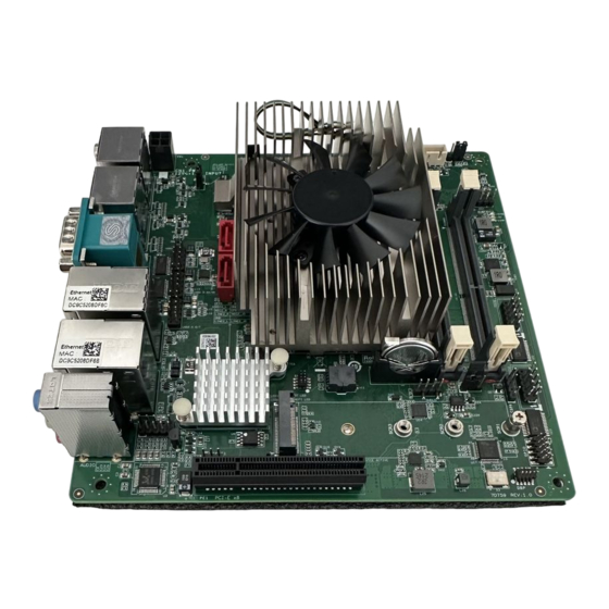
1-2 Mainboard Layout The following figure shows the location of components on the mainboard. See page 6 for component description. Front view of mainboard: 17 18 ~ 4 ~... - Page 10 Back view of mainboard: Note: Picture is for reference only, actual board may be slightly different. See next page for details. ~ 5 ~...
- Page 11 Item Component description AMD FP6 APU DDR4 SO-DIMM *2 PCIe 3.0 x8 Slot M.2 M-key for SSD device 4-pin 12V~19V Power Connector SATA3 Connector *2 (Note) USB 2.0 Header *3 , 2.54mm pitch SATA Power Header, 2.50mm pitch Front Panel Audio Header, 2.54mm pitch S/PDIF Header, 2.54mm pitch Front Panel Header, 2.54mm pitch COM3 Header for RS232 mode, 2.54mm pitch...
-
Page 12: I/O Back Panel
I/O Back Panel COM2 COM1 Item Description Item Description DC-IN 12V~19V Jack 10G bps RJ45 LAN Port (Note) USB2.0 Port *2 Display Port *4 COM Port *2 (RS232/485/422) USB3.1 Gen 2 Port *2 1G bps RJ45 LAN Port Audio Port *3 DC-IN Jack The DC-IN Jack supports only 12V~19V Input. - Page 13 DisplayPort (DP0/DP1/DP2/DP3) The DisplayPort provides support for high resolution displays, digital content protection. With a suitable adapter, DisplayPort may be used to drive displays with a VGA, DVI or HDMI interface. Definition Definition Hot Plug Detect ML_Lane 0 (p) CONFIG1 ML_Lane 0 (n) CONFIG2 ML_Lane 1 (p)
- Page 14 1G bps RJ45 LAN Port The mainboard provides two standard RJ-45 jacks for connecting to Local Area Network (LAN). Two LEDs are built into the RJ-45 LAN connector. These LEDs indicate the status of the LAN. Definition Definition LED Color LED state Indicates LAN link is not established...
- Page 15 USB2.0 Ports (two) The mainboard provides an OHCI/EHCI (Open Host Controller Interface/ Enhanced Host Controller Interface) Universal Serial Bus root for attaching USB devices such as a keyboard, mouse or other USB-compatible devices. Supports data transfer rates up to 480Mb/s. Definition Data- Data+...
-
Page 16: Mainboard Dimension
1-3 Mainboard Dimension PCB Size: 170 x 170mm ~ 11 ~... - Page 17 Cooler size: 98 x 71 x 36.5 mm (For V2748 / V2546) Cooler size: 60 x 60 x 36.9 mm (For V2718 / V2516) ~ 12 ~...
-
Page 18: Chapter 2 Installation
Chapter 2 Installation 2-1 Installing System Memory This mainboard has two 260-pin SO-DIMM sockets (ECC/Non ECC) for DDR4 memory. Supports 4GB, 8GB, 16GB and 32GB DDR4 SO-DIMMs up to maximum 64GB. Supports 1.2V DDR4-2133/2400/2666/2933/3200 DIMMs with dual channel architecture. -
Page 19: Installing Expansion Cards
2-2 Installing Expansion Cards The mainboard provides One PCI Express 3.0 x8 slot One M.2 Slot E-key with 2230 type with PCIe x1 and USB2.0 for Wifi/BT One M.2 Slot M-key with 2242/2260/2280 storage type with PCIe x4 for SSD In front side of mainboard: PE1: PCIe 3.0 x8 slot LED1: When the M.2 slot is in bluetooth mode, this Green LED is on. -
Page 20: Pcie Slot
PCIe Slot The design of this motherboard supports PCIe interface expansion card complying with the PCI Express specification. To install a PCI Express card: 1. Place the card in an available PCI Express slot and press down on the card until it is completely seated in the slot. -
Page 21: M-Key Slot
M.2 M-Key Slot To install the M.2 SSD device: 1. Depending on the length of M.2 SSD device, need to find the corresponding nut location to be used. Remove screws and align the notch on the M.2 SSD device edge connector with the tab in the slot. -
Page 22: Connecting Cables And Jumper Settings
2-3 Connecting Cables and Jumper Settings This section takes you through all the necessary connections on the mainboard. Front Panel Header The front panel header (CFP, 2.00mm pitch) on this motherboard is used to connect the front panel switches and LEDs. PWR_LED Attach the front panel power LED cable to these two pins of the connector. - Page 23 4-pin 12V~19V Power Connector PW1, This power connector is used to provide power to the system. Align the power plug to the connector and press firmly until seated. Definition 12V~19V 12V~19V Note: There are two ways to source power to the board: DC jack or 4-pin power connector.
-
Page 24: Sata Power Header
SATA Power Header The SATA Power header is used to provide 5V and 12V power to SATA3 connector. Definition +12V eDP Connector The mainboard provides one eDP (Embedded DisplayPort ) connector on back side for connect internal panel. Definition Definition +3.3V eDP_VDD(SW_VDD) eDP_BACKVDD (SW_BACK) -
Page 25: Usb2.0 Header
USB2.0 Header This mainboard contains two (2) USB 2.0 ports that are exposed on the rear panel of the chassis and also contains three 10-pin onboard header connectors (2.54mm pitch) that can be used to connect to six (6) external USB 2.0 devices. Definition Definition USB3... -
Page 26: Gpio Header
GPIO Header There is a GPIO (General-purpose input/output) header (2.54mm pitch) on the motherboard. It can connect a variety of simple one- or two-wire devices. Definition Definition SIO_GPIO0(+3.3V) 2 SIO_GPIO4(+3.3V_ALW) SIO_GPIO1(+3.3V) 4 SIO_GPIO5(+1.8V_ALW) SIO_GPIO2(+3.3V_ALW) 6 SIO_GPIO6(+1.8V_ALW) SIO_GPIO3(+3.3V_ALW) 8 SIO_GPIO7(+3.3V_ALW) VCC (+3.3V_ALW) 10 GND Note: +3.3V_ALW means +3.3V Standby Power. -
Page 27: S/Pdif Header
S/PDIF Header This header (2.54mm pitch) is used to connect S/PDIF (Sony & Philips Digital Interconnect Format) interface for digital audio transmission. Definition S/PDIF_Out Speaker Header This header (2.54mm pitch) is used to connect the case’s speaker for PC beeps. Definition Speaker+ Empty... -
Page 28: Jp2 Lcd Backlight Power Jumper
JP2 LCD Backlight Power Jumper You can use JP2 (2.54mm pitch) to select LCD Backlight Voltage. Settings +12V +5V (Default) JP3 LCD VDD Power Jumper You can use JP3 (2.54mm pitch) to select LCD Voltage. Settings +3.3V +5V (Default) JP4 Auto Power ON Jumper You can use JP4 (2.54mm pitch) to select to enable or disable the auto power on function. -
Page 29: System Led Status Indicators
2-4 System LED Status Indicators This mainboard provides three LEDs to indicate the system’s status. STANDBY LED (LED4, Blue): When the System is in Standby Mode, this LED is on. This LED will remain on as long as the motherboard is receiving constant power. -
Page 30: Chapter 3 Configuring The Bios
Chapter 3 Configuring the BIOS This chapter provides information on the BIOS Setup program and allows you to configure the system for optimum use. 3-1 Select Boot Device Select Boot Device Menu allows you to set the first boot device without entering BIOS Setup. - Page 31 Users are welcome to download the latest BIOS version from our official website. Control Keys Please check the following table for the function description of each Control key. Control Key(s) Function Description / Moves cursor left or right to select screens ...
-
Page 32: Main Menu
3-3 Main Menu When entering the Aptio Setup Utility, the main menu screen appears. This main menu includes the system overview and displays the basic system configuration, such as BIOS information, memory size and system date/time. Aptio Setup Utility - Copyright (C) 2021 American Megatrends, Inc. Setup Main Advanced... -
Page 33: Advanced Menu
3-4 Advanced Menu The Advanced menu items allow you to change the settings for the CPU, USB and other system devices. Press <Enter> to display the configuration options. Aptio Setup Utility - Copyright (C) 2021 American Megatrends, Inc. Setup Main Chipset Security Boot... - Page 34 Security Device Support Enables or disables BIOS support for security device. O.S. will not show Security Device. TCG EFI protocol and INT1A interface will not be available. When enabled, the related items will appear. Options: Enabled, Disabled. SHA-1 PCR Bank Enable or disable SHA-1 PCR Bank.
-
Page 35: Acpi Settings
ACPI Settings Aptio Setup Utility - Copyright (C) 2021 American Megatrends, Inc. Setup Advanced ACPI Settings Enables or Disables System ability to Hibernate (OS/S4 Enable Hibernation [Enabled] Sleep State). This option may ACPI Sleep State [S3 (Suspend to RAM)] not be effective with some APU ACPI Shutdown Temperature [Disabled] operating systems. -
Page 36: Hardware Monitor
Hardware Monitor Aptio Setup Utility - Copyright (C) 2021 American Megatrends, Inc. Setup Advanced PC Health Status APU Fan Stopped Working Prompt [Disabled] SmartFan Configuration APU Temperature : +41 System Temperature : +34 APUFAN Speed : 1544 RPM : Select Screen ... - Page 37 Smart Fan Configuration Aptio Setup Utility - Copyright (C) 2021 American Megatrends, Inc. Setup Advanced SmartFan Configuration Fan Mode Setting APUFan Mode Setting [SmartFan] Highest Fan Speed In Percentage 1st Temperature Threshold ( 2nd Fan Speed In Percentage 2nd Temperature Threshold ( : Select Screen ...
-
Page 38: Rtc Wake Settings
RTC Wake Settings Aptio Setup Utility - Copyright (C) 2021 American Megatrends, Inc. Setup Advanced Enable or disable System wake Wake system at specific Time [Disabled] on alarm event. When enabled, System will wake on the Wake System duration after [Disabled] hr::min::sec specified. -
Page 39: Cpu Configuration
CPU Configuration Aptio Setup Utility - Copyright (C) 2021 American Megatrends, Inc. Setup Advanced CPU Configuration Enable or disable No-execute page protection function Module Version: RenoirCpu 08 AGESA Version: RenoirPI 1004 NX Mode [Enabled] SVM Mode [Enabled] : Select Screen ... -
Page 40: Sata Configuration
CPU Information Displays current processor information. Aptio Setup Utility - Copyright (C) 2021 American Megatrends, Inc. Setup Advanced Socket0: AMD Ryzen Embedded V2748 with Radeon Graphics 8 Core(s) Running @ 2932 MHz 1218 mV Processor Family: 17h Processor Model: 60h-6Fh CPUID: 00860F01 Current Speed:2900 MHZ Min Speed:1400 MHZ... -
Page 41: Sio Configuration
SIO Configuration Aptio Setup Utility - Copyright (C) 2021 American Megatrends, Inc. Setup Advanced AMD SIO Driver Version: A5.10.00 View and Set Basic properties of the SIO Logical device. Super IO Chip Logical Device(s) Configuration Like IO Base, IRQ Range, DMA [*Active*] Serial Port 1 Channel and Device Mode. -
Page 42: Usb Configuration
SR-IOV Support If system has SR-IOV capable PCIe devices, this option enables or disables Single Root IO Virtualization support. Options: Enabled, Disabled. USB Configuration Aptio Setup Utility - Copyright (C) 2021 American Megatrends, Inc. Setup Advanced USB Configuration Enables Legacy USB support. USB Module Version AUTO option disables legacy support if no USB devices are... -
Page 43: Network Stack Configuration
Device reset time-out Sets USB mass storage devices start unit command time-out. Options: 10 sec, 20 sec, 30 sec, 40 sec. Device power-up delay Maximum time the device will take before it properly reports itself to the Host controller. ‘Auto’ uses default values: for a Root port it is 100ms, for a Hub port the delay is taken from Hub descriptor. -
Page 44: Csm Configuration
Ipv4 HTTP Support This item is used to enable or disable the Ipv4 HTTP boot support. If disabled, Ipv4 HTTP boot option will not be available. Options: Enabled, Disabled. Ipv6 PXE Support This item is used to enable or disable the Ipv6 PXE boot support. If disabled Ipv6 PXE boot option will not be available. - Page 45 CSM Support This item allows enable or disable the CSM (Compatibility Support Module) configuration. Options: Enabled, Disabled. GateA20 Active This feature determines how Gate A20 is used to address memory above 1MB. Upon Request: GA20 can be disabled using BIOS services. Always: Do not allow disabling GA20.
-
Page 46: Nvme Configuration
NVMe Configuration Aptio Setup Utility - Copyright (C) 2021 American Megatrends, Inc. Setup Advanced NVMe Configuration Samsung SSD 970 EV0 Plus 250GB : Select Screen Select Item Enter: Select +/-: Change Opt. General Help Previous Values F3/F9: Optimized Defaults F4/F10:Save and Exit ESC: Exit... - Page 47 M.2 E-Key Socket (PCIE x1) Allows you to enable or disable the M.2 E-Key Socket. Options: Disabled, Enabled. M.2 M-Key Socket (PCIE x4) Allows you to enable or disable the M.2 M-Key Socket. Options: Disabled, Enabled. HD Audio Azalia Device Allows you to enable or disable the onboard High Definition Audio controller.
-
Page 48: Amd Cbs
AMD CBS Aptio Setup Utility - Copyright (C) 2021 American Megatrends, Inc. Setup Advanced AMD CBS CPU Common Options CPU Common Options UMC Common Options NBIO Common Options FCH Common Options : Select Screen Select Item Enter: Select +/-: Change Opt. - Page 49 UMC Common Options DDR4 Common Options DRAM Timing Configuration Aptio Setup Utility - Copyright (C) 2021 American Megatrends, Inc. Setup Advanced DRAM Timing Configuration I Accept WARNING - DAMAGE CAUSED BY USE OF YOUR AMD PROCESSOR OUTSIDE OF SPECIFICATION OR IN EXCESS OF FACTORY SETTINGS ARE NOT COVERED UNDER YOUR AMD PRODUCT WARRANTY AND MAY NOT BE CONVERED BY YOUR SYSTEM...
- Page 50 Common RAS ECC Configuration DRAM ECC Symbol Size Use this option to select the DRAM ECC Symbol Size. Options: x4, x8, Auto. DRAM ECC Enable Use this option to enable/disable DRAM ECC. Auto will set ECC to enable. Options: Enabled, Disabled, Auto. DRAM UECC Retry Use this option to enable/disable DRAM UECC Retry.
- Page 51 display resolution. Options: 1920x1080 and below, 2560x1600, 3840x2160, Auto. Audio Configuration DP/HDMI Audio Allows you to enable or disable the Integrated HD Audio Controller. Options: Disabled, Enabled, Auto SMU Common Options System Configuration This item allows you to select the System Configuration. Options: 10W POR Configuration 15W POR Configuration...
-
Page 52: Amd Pbs
AMD PBS Aptio Setup Utility - Copyright (C) 2021 American Megatrends, Inc. Setup Advanced AMD Firmware Version Show all of AMD Firmware Version Primary Video Adaptor [Ext Graphics (PEG)] : Select Screen Select Item Enter: Select +/-: Change Opt. General Help Previous Values F3/F9: Optimized Defaults... -
Page 53: Chipset Menu
3-5 Chipset Menu The chipset menu items allow you to change the advanced chipset settings. Press <Enter> to display the sub-menu. Aptio Setup Utility - Copyright (C) 2021 American Megatrends, Inc. Setup Main Advanced Security Boot Save & Exit Chipset South Bridge Parameters South Bridge North Bridge... -
Page 54: North Bridge
USB2.0 Port 1 (USB2_P6_P7 Header) / USB2.0 Port 2 (USB2_P6_P7 Header) / USB2.0 Hub (USB2_A_B & USB2_C_D Header) Allows you to enable or disable USB ports. Options: Enabled, Disabled. North Bridge Aptio Setup Utility - Copyright (C) 2021 American Megatrends, Inc. Setup Chipset North Bridge Configuration... -
Page 55: Security Menu
3-6 Security Menu The Security menu allows you to change the system security settings. Aptio Setup Utility - Copyright (C) 2021 American Megatrends, Inc. Setup Main Advanced Chipset Boot Save & Exit Security Password Description Set Administrator Password. If ONLY the Administrator’s password is set, then this only limits access to Setup and is only asked for when entering Setup. -
Page 56: Boot Menu
3-7 Boot Menu The Boot menu is used to configure the boot settings and the boot priority. Aptio Setup Utility - Copyright (C) 2021 American Megatrends, Inc. Setup Main Advanced Chipset Security Save & Exit Boot Boot Configuration Number of seconds to wait for Setup Prompt Timeout setup activation key. -
Page 57: Save & Exit Menu
3-8 Save & Exit Menu The Save & Exit menu allows you to load the optimal default values for BIOS, and save or discard your changes to the BIOS items. Aptio Setup Utility - Copyright (C) 2021 American Megatrends, Inc. Setup Main Advanced... -
Page 58: Driver Install
Chapter 4 Driver Installation After the operating system has been installed, you need to install drivers for this mainboard. The support DVD that came with the motherboard contains necessary drivers and useful utilities that enhance the motherboard features. 4-1 Driver Install Insert the bundled driver DVD into your optical drive and the main menu will be displayed on your PC screen.
Need help?
Do you have a question about the IPC-FP6 and is the answer not in the manual?
Questions and answers