
Related Manuals for Powercom 325A


Summary of Contents for Powercom 325A
- Page 1 U P S Uninterruptible Power System Line Interactive UPS 325A/425A/525A/625A Line Interactive Network UPS 425AP/525AP/625AP USER‘S MANUAL...
-
Page 2: Important Safety Instructions
Important safety instructions __________________________________________________________ _____ Thank you for selecting this uninterruptible power system (UPS). It provides you with better protection for connected equipment. Please read this manual! This manual provides safety, installation and operating instructions that will help you derive the fullest performance and service life that the UPS has to offer. -
Page 3: Table Of Contents
Table of contents __________________________________________________________ ____ 1 . I n t r o d u c t i o n … … … … … … … … … … … … … … . . 1 2 . S a f e t y … … … … … … … … … … … … … … … … … 2 3. -
Page 4: 1. Introduction
1. INTRODUCTION __________________________________________________________ _____ The product is line interactive UPS with the newest technology and powerful function. The LINE INTERACTIVE ups is with AVR function allows input voltage range from 75% to 125%, including on line voltage boost-up & buck down. An ideal protection equipment for critical connected loads. -
Page 5: Safety
2. Safety __________________________________________________________ _____ ● To reduce the risk of electric shock, disconnect the UPS from the mains supply before installing a computer interface signal cable. Reconnect the power cord only after signaling interconnections have been made. ● The internal energy source(the battery) cannot be de-energized by the user. -
Page 6: Presentation
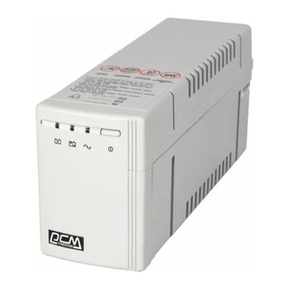
3. Presentation __________________________________________________________ ____ FRONT PANEL 3.1 "REPLACE BATTERY" indicator (RED LED) The LED illuminates when the UPS's battery is no longer useful and must be replaced. Note: When replace battery, disconnect the utility power then open the case and take notice of the battery's polarity while install the new battery to avoid short. -
Page 7: Rear Panel
__________________________________________________________ REAR PANEL 3.5 COMPUTER INTERFACE (425AP/525AP/625AP models only) Provide both RS-232 and relay signal to support NOVELL, UNIX, DOS, WINDOWS and other operating systems. 3.6 OUTPUT POWER RECEPTACLES 3.7 AC INPUT POWER RECEPTACLE 3.8 TEL./MODEM SURGE PROTECTION (425AP/525AP/625AP models only) Surge protection for telephone and modem line to have the complete safety connection for INTERNET service. -
Page 8: Installation
4. Installation __________________________________________________________ ____ 4.0 Inspection Inspect the UPS upon receipt. The packaging is recyclable; save it for reuse or dispose of it properly. 4.1 Placement Install the UPS in a protected area with adequate air flow and free of excessive dust. -
Page 9: 5 . 面 板 功
4.5 Connect the loads Plug the loads into the output connectors on the rear of the UPS. To use the UPS as a master on/off switch, make sure all of the loads are switched on. Caution: Never connect a laser printer or plotter to the UPS with other computer equipment. -
Page 10: Operation
5. Operation __________________________________________________________ ____ 5.1 Switch on With the UPS plugged in, press and hold the on/off/test/silence button more than 1 second until "LINE NORMAL" LED lit to switch the ups on. The UPS will perform self-testing each time when it is switched on. Note: When switched off the UPS maintains the battery charge and will respond to commands received through the computer interface port. -
Page 11: Alarm
6. Alarm __________________________________________________________ _____ 6.1 "BACK UP" (slow alarm) When in BACK UP mode, the YELLOW LED illuminates and the UPS sounds an audible alarm. The alarm stops when the UPS returns to LINE NORMAL operation. Press the on/off/test/silence button during on-battery alarms to stop the beeping. -
Page 12: Software Options
7. Software options __________________________________________________________ ____ 7.1 UPSMON Software The UPSMON software is applied standard RS-232 interface to perform monitoring functions, and then provides an orderly shutdown of a computer in the event of power failure. Moreover, UPSMON displays all the diagnostic symptoms on monitor, such as Voltage, Frequency, Battery level and so on.. -
Page 13: C O M P U T E R I N T E R F A C E P O R
8. Computer Interface Port __________________________________________________________ ____ The computer interface port has the following characteristics:... -
Page 14: B A T T E R Y R E P L A C E M E N
9. Battery Replacement __________________________________________________________ ____ Your battery should run any where from 3-5 years before eve needing to be replaced. Please follow the instructions below for easy battery replacement. 1) Unplug unit from AC power source and disconnect all connected equipment. 2) Disconnect AC power cord from unit.. -
Page 15: Troubleshooting
10. Troubleshooting __________________________________________________________ ____ PROBLEM POSSIBLE CAUSE UPS not on On/off/test/silence LED not light button not pushed or push too short Battery voltage less than PCB failure Load less than 20W at battery mode UPS always at Power cord lose battery mode AC FUSE burn out Line voltage too high, too... -
Page 16: Specifications
EMI/RFI filter Overload Protection Unit Input 10Baase-T Cable Port Short Circuit BATTERY Type 325A 425A(P) 525A(P) 325VA 425VA 525VA 100V, 110V, 120V, 220V, 232V, 240V, +/-25% 50 or 60Hz +/-5% (auto sensing) Simulated sine wave at Line Input +/-5% 50 or 60Hz +/-0.5% AVR automatically increase output voltage 15% above input voltage if -9% to-25% of nominal. - Page 17 Audible noise Storage condition ©1997 Powercom Co., Ltd. All right Reserved. All trademarks are property of their respective owners. Specifications subject to change without notice. 4 hours (to 90% of full capacity) Automatic self-test & discharge protection, replace battery...
Need help?
Do you have a question about the 325A and is the answer not in the manual?
Questions and answers