Advertisement
Quick Links
EHPS-...-LK
Parallel gripper
Operating instructions
8154967
2021-05a
[8154969]
Translation of the original instructions
© 2021 all rights reserved to Festo SE & Co. KG
IO-Link® is a registered trademark of its respective trademark holder in certain
countries.
1
Applicable Documents
All available documents for the product è www.festo.com/sp.
2
Product labelling
Warning symbols on the product
If the housing is damaged, protection against dangerous voltages is no longer
guaranteed.
Tab. 1: Warning symbols on the product
3
Safety
3.1
Safety instructions
– Observe labelling on the product.
– Before working on the product: Switch off the power supply, ensure that it is off
and secure it against being switched on again.
– The occurrence of a failure could lead to unforeseeable movements if the
product is connected with the power supply. Only operate the product once
protective measures have been taken against mechanical hazards to body
parts.
– Observe tightening torques. Unless otherwise specified, the tolerance is
± 20 %.
– Contrary to the specification IO-Link port class B without galvanic isolation
between primary and secondary power supply. This can lead to malfunction or
damage to the IO-Link Master and the connected IO-Link devices and must be
observed during wiring.
3.2
Intended use
The intended use of the product is to grip and hold payloads (workpieces) using
custom-designed gripper fingers attached by the customer.
3.3
Foreseeable misuse
When not used as intended, the product-supported protection can be impaired.
3.4
Training of qualified personnel
Work on the product may only be carried out by qualified personnel who can
evaluate the work and detect dangers. The qualified personnel have skills and
experience in dealing with electrical (open-loop) control technology.
4
Additional information
– Accessories è www.festo.com/catalogue.
5
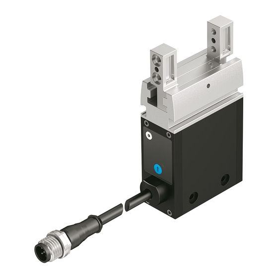
Product overview
5.1
Function
The gripper has an integrated servo motor. The gripper mechanism converts the
rotary motion of the servo motor into a linear motion of the gripper jaws.
The gripper jaws move towards one another (closing) or apart (opening). Gripper
fingers are fastened to the gripper jaws.
The payload can be gripped in 2 ways:
– on the external contour (external gripping) when closing
– on the internal contour (internal gripping) when opening
The parallel gripper is controlled via an IO-Link interface.
5.2
8
Festo SE & Co. KG
Ruiter Straße 82
73734 Esslingen
7
Deutschland
6
+49 711 347-0
www.festo.com
5
Fig. 1: Product design
6
– Store the product in a cool, dry environment protected from UV and corrosion.
Keep storage times short.
7
7.1
The gripper fingers are not included in the delivery.
Requirements for the gripper fingers è Technical data:
– Observe the max. permissible forces and max. permissible torques at the
gripper jaw.
– Observe the max. length and max. weight.
– Use gripper fingers that are as short and light as possible.
– Manufacture gripper fingers that are suitable for the payload and type of grip-
ping action.
7.2
3
2
1
Fig. 2: Gripper finger mounting
1. Press centring pin [2] or centring sleeve into the locating holes in the gripper
jaws.
2. Position the prepared gripper fingers [3] on the gripper jaws and secure with
2 screws [1] on each. Fix gripper jaws in place during mounting and use the
specified tightening torque.
Structure
1
2
3
4
Transport and storage
Assembly
Preparing the gripper fingers
Mounting the gripper fingers
EHPS
Screw
Centring hole for centring
[mm]
sleeve [H8]
Centring hole for centring pin
[mm]
[H8]
Jaw width
[mm]
Tightening torque (brace at
[Nm]
gripper jaws)
Gripper jaw
1
2
Slot for proximity switch
Locating hole and thread for
3
mounting
Electrical connection
4
5
LED ready
LED Error
6
7
Plug screw
8
Locating hole and thread for
gripper finger mounting
Screw
1
2
Centring pin
Gripper finger
3
-16
-20
-25
M4
M4
M5
7
7
9
3
4
4
10 ± 0.05
12 ± 0.05
15 ± 0.05
2.9
2.9
5.9
Advertisement

Related Manuals for Festo EHPS LK Series


Summary of Contents for Festo EHPS LK Series
- Page 1 Translation of the original instructions Preparing the gripper fingers © 2021 all rights reserved to Festo SE & Co. KG IO-Link® is a registered trademark of its respective trademark holder in certain The gripper fingers are not included in the delivery.
-
Page 2: Installation
Tightening torque [Nm] 5 (GY) 0 V DC Actuator: supply voltage grey Through-hole mounting 1) Wire colour with use of connecting cables according to accessories è www.festo.com/catalogue Screw Tab. 3: Pin allocation Centring hole [mm] Tightening torque [Nm] Commissioning Tab. -
Page 3: Specification
51/0x000033 333/0x014D Tab. 6: Identification parameters Index Subindex Name Value Length Format (example) [byte] 0x0010 ‘Vendor Name’ Festo SE & Co. KG String è 0x0011 ‘Vendor Text’ www.festo.com 64 String 0x0012 ‘Product Name’ EHPS-16-A-LK String EHPS-20-A-LK EHPS-25-A-LK Fig. 5: Data exchange 0x0013 ‘Product ID’... - Page 4 ‘ResetDirectionFlag’ (bit 50) ‘ClosedPositionFlag’ (bit 42) The gripper stores the last travelled direction. After the ‘Close’ command, the Active when the gripper has reached the closed position. In the case of a previous ‘Open’ command must follow and vice versa. If, for example, it is necessary to redefinition of the end position, the bit always becomes active when the gripper move the jaws in the same direction when changing a workpiece, the direction has reached this stored position or is further closed.
- Page 5 Index Subindex Name Descrip- Value Lengt Format Force level Decimal value Force value tion (example Invalid – [byte] Level 1 approx. 50% – Invalid – 0 0x0105 ‘Gripping- UIntegerT8 Level 2 approx. 70% – Gripping – 1 Force’ – 2 force Level 3 approx.
- Page 6 SE & Co. KG longer be high cooling/ 0x406 (1030) Failure ‘System error / Internal Service Festo – Gripper has moved) connection internal error’ system error SE & Co. KG overload 1) Incrementing the "ErrorCount" parameter for these messages...
-
Page 7: Fault Description
2. Rotate the worm shaft underneath using the hex wrench until the jamming is resolved: – Anti-clockwise (external gripping) – Clockwise (internal gripping) 3. Retighten plug screw. EHPS Hex wrench ß 1.5 ß 1.5 ß 2 Tightening torque for plug [Nm] screw 12.3 Repair Send product to the Festo repair service for repair. - Page 8 14.2 Characteristic curves Lever arm x Vertical Horizontal Fig. 11: EHPS-16 internal gripping, lever arm horizontal Force class 1 Force class 3 Force class 2 Force class 4 Tab. 29: Alignment of lever arm x The forces refer exclusively to centric gripping of non-elastic components. Total gripping force F (2x jaw gripping force) as a function of lever arm x and force class...
- Page 9 Fig. 15: EHPS-20 internal gripping, lever arm horizontal Fig. 19: EHPS-25 internal gripping, lever arm horizontal Force class 1 Force class 3 Force class 1 Force class 3 Force class 2 Force class 4 Force class 2 Force class 4 Fig.
Need help?
Do you have a question about the EHPS LK Series and is the answer not in the manual?
Questions and answers