Table of Contents
Advertisement
Quick Links
Advertisement
Table of Contents

Subscribe to Our Youtube Channel
Related Manuals for VESTEL EVC03 Series


Summary of Contents for VESTEL EVC03 Series
- Page 1 ELECTRIC VEHICLE CHARGER EVC03 Series Installation Guideline...
-
Page 2: Table Of Contents
4.7.1 - GENERAL SETTINGS..............28 4.7.2 - OCPP SETTINGS..............30 4.7.3 - NETWORK INTERFACES SETTINGS........34 4.7.4 - STANDALONE MODE SETTINGS..........35 4.7.5 - SYSTEM MAINTENANCE PAGE ...........36 4.8 - CLOSE COVER ..................37 IB v1.0 2020 © 2020 Vestel - All rights reserved English - 1... -
Page 3: Safety Information
SAFETY INFORMATION CAUTION RISK OF ELECTRIC SHOCK: CAUTION: VESTEL ELECTRIC VEHICLE CHARGER DEVICE SHALL BE MOUNTED BY A LICENSED OR AN EXPERIENCED ELECTRICIAN AS PER ANY REGIONAL OR NATIONAL ELECTRIC REGULATIONS AND STANDARDS IN EFFECT. CAUTION AC grid connection and load planning of the electric vehicle charging device shall be reviewed and approved by authorities as specified by the regional or national electric regulations and standards in effect. -
Page 4: Ground Connection Warnings
• Use appropriate protection when connecting to the main power distribution cable. IB v1.0 2020 © 2020 Vestel - All rights reserved English - 3... -
Page 5: Required Upstream Protections
MCCB (Thermic Magnetic Adjustable) must be connected to the upstream distribution box. EVC03- 180kW+65kVA 500 A 370A DC180 180kW+65kVA EVC03- 400 A 120kW+65kVA 274A DC120 EVC03- 250A 60kW+65kVA 188A DC60 IB v1.0 2020 © 2020 Vestel - All rights reserved English - 4... -
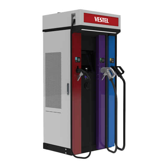
Page 6: Description
DC CCS Outlet DC CHAdeMO Outlet AC 43kW Outlet AC 22kW Socket Outlet Access cover for CTB, PLC Board and HMI, Power Modules IB v1.0 2020 © 2020 Vestel - All rights reserved English - 5... -
Page 7: Dimensional Drawings
2 - DIMENSIONAL DRAWINGS Front and Side View Figure.1 Top View Figure.2 IB v1.0 2020 © 2020 Vestel - All rights reserved English - 6... -
Page 8: Electric Vehicle Charging Station Exploded Picture
3 - ELECTRIC VEHICLE CHARGING STATION EXPLODED PICTURE Figure-3 IB v1.0 2020 © 2020 Vestel - All rights reserved English - 7... - Page 9 Diffuser Roof Parts Chademo Cover Parts Right Cover Parts Chademo Gun Grill Right Parts CCS Cover Parts Filter Parts CCS Cover Gun Filter Frame Parts Frame HMI V2 IB v1.0 2020 © 2020 Vestel - All rights reserved English - 8...
-
Page 10: Required Equipment, Tools And Accessories
2 - RECOMMENDED EQUIPMENTS and TOOLS Ø20 Drill Bit Impact Drill Philips Screwdriver RJ45 Crimping Tool Cat5e or cat6 ethernet cable 13(M8) , 17(M10), Hammer 19(M12) Spanner IB v1.0 2020 © 2020 Vestel - All rights reserved English - 9... -
Page 11: Electrical Specification
Internal Protections Over Temperature / Surge Protection USER INTERFACE & AUTHENTICATION Display 10” Color TFT LCD User Interface Resistive Touch Screen RFID Reader Module ISO-14443A/B and ISO-15693 IB v1.0 2020 © 2020 Vestel - All rights reserved English - 10... -
Page 12: Connectivity
WARNING: TO AVOID PERSONAL INJURY OR DAMAGE THE CHARGING STATION, ENSURE THE INSTALLATION AREA IS SUITABLE AND THE FLOOR CAN WITHSTAND THE WEIGHT OF THE CHARGING STATION. IB v1.0 2020 © 2020 Vestel - All rights reserved English - 11... -
Page 13: Unpack Charging Station
1 - UNPACK CHARGING STATION Unpack the charging station as shown in figure below. Note that, front and top covers are marked as shown in the figures. Figure.1 IB v1.0 2020 © 2020 Vestel - All rights reserved English - 12... -
Page 14: Box Contents For Charging Station
2 - BOX CONTENTS FOR CHARGING STATION Installation and User Guide User RFID Cards ELECTRIC VEHICLE CHARGER EVC03 Series User Manual ELECTRIC VEHICLE CHARGER EVC03 Series User Manual Figure.2 IB v1.0 2020 © 2020 Vestel - All rights reserved English - 13... -
Page 15: Foundation, Alingment & Placement
For these 4 options; The position and diameter of the cable duct are shown at Figure-4 4- The top surface of the foundation must be at least 20 mm above the ground. (See Figure-4) IB v1.0 2020 © 2020 Vestel - All rights reserved English - 14... - Page 16 7- Drill 4 holes on the concrete foundation with dimensions shown at Figure.4 and tap M20x170 mm expansion bolt in these holes stated as shown at Figure-7. IB v1.0 2020 © 2020 Vestel - All rights reserved English - 15...
- Page 17 8- Remove the (left and right) bottom side plates by unscrewing the plates. Figure.5 IB v1.0 2020 © 2020 Vestel - All rights reserved English - 16...
- Page 18 The type of expansion bolts used are shown at Figure-7. 514mm 800mm 577mm FRONT VIEW RIGHT VIEW Figure.6 Holes Drill Diameter : Ø20 mm, Drill Depth : 155 mm (Torque: 480Nm) Figure.7 Figure.8 IB v1.0 2020 © 2020 Vestel - All rights reserved English - 17...
- Page 19 10- Remove the eyebolts after placement of the charging station. Plug the bolts with the washers. Figure.9 You can continue following “Cable Installation” steps IB v1.0 2020 © 2020 Vestel - All rights reserved English - 18...
-
Page 20: Opening Side Covers
Use the key provided to unlock the side cover. Pull the handle slightly up. Turn the handle through the back side of the charging station with wide-angle. Figure.10 IB v1.0 2020 © 2020 Vestel - All rights reserved English - 19... -
Page 21: Cable Installation
Therefore the center points of the cable glands and the crimping lugs are aligned with the same axis (z-axis) as shown in the figure. The installation must be done accordingly as shown in the figure. IB v1.0 2020 © 2020 Vestel - All rights reserved English - 20... - Page 22 4- Connect the AC Mains cables. First connect “Line PE” cable, then “Line N” cable, finally three phase cables (“Line 1”, “Line 2”, “Line 3”) as shown below: The phase sequence is counter clockwise rotation. IB v1.0 2020 © 2020 Vestel - All rights reserved English - 21...
- Page 23 Figure.14 Line 3 Line 2 Line 1 Neutral 5- Tighten the cable glands using an adjustable wrench. IB v1.0 2020 © 2020 Vestel - All rights reserved English - 22...
-
Page 24: Sim Card Connection
Figure.15 4.3 - CONNECT OCPP OVER ETHERNET Insert cable through the cable gland. Pull the cable through the cable clamps as indicated by arrows in below figure. IB v1.0 2020 © 2020 Vestel - All rights reserved English - 23... - Page 25 The closer se the handles and repeat this step to ensure the wire ends are trimmed, the better your a proper crimp. final plug-in connection will be. IB v1.0 2020 © 2020 Vestel - All rights reserved English - 24...
-
Page 26: Connect Pc To The Same Network With Hmi Board
You should assign static IP address to your PC in 192.168.0.0/254 network which means that IP address should be in a range of between 192.168.0.1 and 192.168.0.254 . For example, 192.168.0.11 can be set as an static IP to your PC. IB v1.0 2020 © 2020 Vestel - All rights reserved English - 25... -
Page 27: Open Web Config Ui With Browser
You will see the following page which is not an error. This is a certificate warning and is not important. Press the advanced button. Figure.18 Press proceeding to continue. IB v1.0 2020 © 2020 Vestel - All rights reserved English - 26... -
Page 28: Main Page
You can change the language of the UI by making selection from the drop down menu on the right corner. You can log out whenever you want by clicking “Log out” button on the top right corner of the page. IB v1.0 2020 © 2020 Vestel - All rights reserved English - 27... -
Page 29: Make Settings Change In Web Config Ui
Figure.21 4.7 MAKE SETTINGS CHANGE IN WEB CONFIG UI 4.7.1 GENERAL SETTINGS You can reach Display Language, Display Settings, Connector Settings under General Settings. Figure.22 IB v1.0 2020 © 2020 Vestel - All rights reserved English - 28... - Page 30 Figure.23 Figure.24 IB v1.0 2020 © 2020 Vestel - All rights reserved English - 29...
-
Page 31: Ocpp Settings
Authorize All: Requires an IdTag to be presented, however does not check its integrity; it accepts all IdTags. Authorize with Whitelist: Only accepts the IdTags that are preset; rejects others. Figure.25 Figure.26 IB v1.0 2020 © 2020 Vestel - All rights reserved English - 30... - Page 32 In case of the auto option, the interfaces have a priority (Ethernet -> Wifi -> Cellular). The most prior interface which has an IP is the selected interface for Server Connection. Figure.27 IB v1.0 2020 © 2020 Vestel - All rights reserved English - 31...
- Page 33 These parameters are based on the definitions at the OCPP 1.6 Specification. These may be modified by the server if the config is not read-only. This interface gives the capability of changing both the read-write and the read-only configumrations. IB v1.0 2020 © 2020 Vestel - All rights reserved English - 32...
- Page 34 Figure.28 IB v1.0 2020 © 2020 Vestel - All rights reserved English - 33...
-
Page 35: Network Interfaces Settings
If you set Wi-Fi as enabled, “SSID”, “Password” and “Security” are mandatory. You should fill all spaces in suitable formats. When you finish it, click “Save” button. Figure.29 Figure.30 IB v1.0 2020 © 2020 Vestel - All rights reserved English - 34... -
Page 36: Standalone Mode Settings
Figure.31 4.7.4 STANDALONE MODE SETTINGS If you are done with mode selection, click “Save” button. Figure.32 IB v1.0 2020 © 2020 Vestel - All rights reserved English - 35... -
Page 37: System Maintenance Page
4.7.5 SYSTEM MAINTENANCE PAGE In diagnostics page, you can download OCPP or HMI logs by clicking buttons. Download dialog will be shown after a few seconds. Figure.34 IB v1.0 2020 © 2020 Vestel - All rights reserved English - 36... -
Page 38: Close Cover
5- Close the right side cover of the product by turning the handle clockwise with a wide-angle as shown in the section “Opening side covers“using the keys provided. IB v1.0 2020 © 2020 Vestel - All rights reserved English - 37... - Page 39 VESTEL KOMÜNİKASYON SANAYİ VE TİCARET A.Ş. Ege Serbest Bölgesi Akçay Caddesi Ayfer Sokak No:144/1 Gaziemir-İzmir / TÜRKİYE Telefon (pbx) : 90 (232) 251 72 90 Fax : 90 (232) 251 73 13 Gaziemir V.D. : 837 001 0241...
Need help?
Do you have a question about the EVC03 Series and is the answer not in the manual?
Questions and answers