Emerson Rosemount 2130 Quick Start Manual
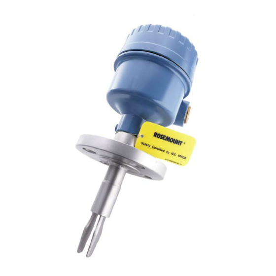
Level switch
Hide thumbs
Also See for Rosemount 2130:
- Reference manual (78 pages) ,
- Quick start manual (41 pages) ,
- Functional safety manual (26 pages)

Related Manuals for Emerson Rosemount 2130


Summary of Contents for Emerson Rosemount 2130
- Page 1 Quick Start Guide 00825-0100-4130, Rev DB May 2022 ™ Rosemount 2130 Level Switch Vibrating Fork...
-
Page 2: Table Of Contents
Quick Start Guide May 2022 Contents About this guide...........................3 Installation........................... 5 Prepare the electrical connections....................11 Connect wiring and power up.....................27 Configuration..........................30 Operation...........................33 Quick Start Guide... -
Page 3: About This Guide
May 2022 Quick Start Guide About this guide This Quick Start Guide provides basic guidelines for the Rosemount 2130. Refer to the Rosemount 2130 Reference Manual for more instructions. The manual and this guide are also available electronically at Emerson.com/Rosemount. - Page 4 Quick Start Guide May 2022 WARNING Electrical shock could cause death or serious injury. Avoid contact with the leads and terminals. High voltage that may be present on leads can cause electrical shock. Ensure the power to the level switch is off, and the lines to any other external power source are disconnected or not powered while wiring the level switch.
-
Page 5: Installation
May 2022 Quick Start Guide Installation Fork alignment in a pipe installation The fork is correctly aligned by positioning the groove or notch as indicated (Figure 2-1). Figure 2-1: Correct Fork Alignment for Pipe Installation A. Tri Clamp process connections have a circular notch B. - Page 6 Quick Start Guide May 2022 Mounting the threaded version 2.3.1 Threaded vessel (tank) or pipework connection Procedure 1. Seal and protect the threads. Use anti-seize paste or PTFE tape according to site procedures. A gasket may be used as a sealant for BSPP (G) threaded connections. 2.
- Page 7 May 2022 Quick Start Guide 2.3.2 Threaded flange connection Procedure 1. Place the customer-supplied flange and gasket on the vessel (tank) nozzle. A. Gasket (customer supplied) 2. Tighten the bolts and nuts with sufficient torque for the flange and gasket. 3.
- Page 8 Quick Start Guide May 2022 4. Screw the level switch into the flange thread. Note Tighten using the hexagon nut only. A. Gasket for BSPP (G) threaded connection Mounting the flanged version Procedure 1. Lower the level switch into the nozzle. A.
- Page 9 May 2022 Quick Start Guide 2. Tighten the bolts and nuts with sufficient torque for the flange and gasket. Mounting the Tri Clamp version Procedure 1. Lower the level switch into the flange face. A. Seal (supplied with Tri Clamp) Quick Start Guide...
- Page 10 Quick Start Guide May 2022 2. Fit the Tri Clamp. Quick Start Guide...
-
Page 11: Prepare The Electrical Connections
8/16 mA electronics: 24 Vdc Hazardous areas When the device is installed in hazardous areas (classified locations), local regulations and the conditions-of-use specified in applicable certificates must be observed. Review the Rosemount 2130 Product Certifications document for information. Quick Start Guide... - Page 12 Quick Start Guide May 2022 Wiring diagrams CAUTION • Before use, check the cable glands and blanking plugs are suitably rated. • Isolate supply before connecting the switch or removing the electronics. • The Protective Earth (PE) terminal must be connected to an external earthing system.
- Page 13 May 2022 Quick Start Guide 3.5.1 Direct load switching cassette Figure 3-1: Direct Load Switching (2-wire) Cassette (Red Label) – Code L Fuse 2A(T) DPST R = External load (must be fitted) N = Neutral L = Live Note A DPST (Double Pole, Single Throw) on/off switch must be fitted for safe disconnection of the power supply.
- Page 14 Quick Start Guide May 2022 Table 3-2: Direct Load Functions Mode: dry on, high level alarm Mode: wet on, low level alarm < 4 mA < 4 mA 12 V 12 V DPST DPST DPST DPST LED on continuously LED flashes every LED on continuously LED flashes every second...
- Page 15 May 2022 Quick Start Guide 3.5.2 PNP/PLC cassette Figure 3-2: PNP/PLC (3-wire) Cassette (Yellow Label) – Code P Wet On Mode O/P 0V F = Fuse 2A(T) Table 3-3: Electrical Parameters Parameter Value 20 - 60 Vdc < 4 mA + I <...
- Page 16 Quick Start Guide May 2022 Table 3-4: PNP/PLC Cassette Functions Mode: dry on, high level alarm Mode: wet on, low level alarm PLC (positive input) <100 μA <100 μA < 3 V < 3 V PNP dc < 3 V <...
- Page 17 May 2022 Quick Start Guide 3.5.3 Relay DPCO cassette (standard version) Figure 3-3: Relay DPCO Cassette, Standard Version (Green Label) – Code OPERATION MODE Warning Isolate Supply Before Removing Seconds Delay Dry On Dr y On Wet On Wet On Fuse 0.5 (T) DPST Note...
- Page 18 Quick Start Guide May 2022 Table 3-6: NC, C, and NO Terminals Parameter Resistive load Inductive load cos ϕ 0 ms 7 ms 3.5 A 250 V 250 V 30 V 30 V 1250 VA 875 VA 240 W 170 W Table 3-7: Relay Cassette Functions Mode: dry on, high level alarm Mode: wet on, low level alarm...
- Page 19 May 2022 Quick Start Guide 3.5.4 Fault and alarm relays (2 x SPCO) cassette Figure 3-4: Fault and Alarm Relay Outputs Cassette (Light Green Label) – Code D with Option R2264 Fuse 0.5 (T) DPST Live Note A Double Pole, Single Throw on/off switch must be fitted for safe disconnection of the power supply.
- Page 20 Quick Start Guide May 2022 Table 3-9: NC, C, and NO Terminals Parameter Resistive load Inductive load cos ϕ 0 ms 7 ms 3.5 A 250 V 250 V 30 V 30 V 1250 VA 875 VA 240 W 170 W Table 3-10: Relay Cassette Functions Mode: dry on, high level alarm Mode: wet on, low level alarm...
- Page 21 Figure 3-5: NAMUR Cassette (Light Blue Label) – Code N A. A certified intrinsically safe isolating amplifier to IEC 60947-5-6 Note • This cassette is suitable for Intrinsically Safe (IS) applications and requires a certified isolating barrier. See the Rosemount 2130 Product Certifications document for Intrinsically Safe approvals. •...
- Page 22 Quick Start Guide May 2022 Table 3-12: NAMUR Cassette Functions Mode: dry on, high level alarm Mode: wet on, low level alarm > 2.2 mA < 1.0 mA > 2.2 mA < 1.0 mA LED on continuously LED flashes every LED on continuously LED flashes every second...
- Page 23 Figure 3-6: 8/16 mA Cassette (Dark Blue Label) – Code M A. A certified intrinsically safe isolating amplifier to IEC 60947-5-6 Note • This cassette is suitable for Intrinsically Safe (IS) applications and requires a certified isolating barrier. See the Rosemount 2130 Product Certifications document for Intrinsically Safe approvals. •...
- Page 24 Quick Start Guide May 2022 Table 3-14: 8/16 mA Cassette Functions Mode: dry on, high level alarm Mode: wet on, low level alarm > 15 mA < 8.5 mA > 15 mA < 8.5 mA LED on continuously LED flashes every LED on continuously LED flashes every second...
- Page 25 May 2022 Quick Start Guide 3.5.7 Fault condition detection (self-check mode only) When a fault condition is detected in the self-check operating mode, the heartbeat LED flashes once every half a second and every third flash is missed. The output from the level switch will then be as Table 3-15.
- Page 26 Quick Start Guide May 2022 Grounding Make sure grounding is done according to national and local electrical codes. Failure to do so may impair the protection provided by the equipment. 3.6.1 Signal cable shield grounding Make sure the instrument cable shield is: •...
-
Page 27: Connect Wiring And Power Up
The cover must also not to be removed in extreme environmental conditions. Versions of the Rosemount 2130 with explosion-proof/flameproof approvals have a cover-lock to be undone first. 3. Remove the plastic plugs. - Page 28 Quick Start Guide May 2022 5. Connect the cable wires (see Wiring diagrams for other cassettes). 6. Ensure proper grounding. 7. Tighten the cable glands. Apply PTFE tape or other sealant to the threads. Note Make sure to arrange the wiring with a drip loop. 8.
- Page 29 May 2022 Quick Start Guide 9. Attach and tighten the cover. Make sure the cover is fully engaged. Required for explosion-proof/flameproof installations only: The cover must be fully engaged to comply with explosion-proof requirements. 11. Re-lock the cover. 12. Connect the power supply. Quick Start Guide...
-
Page 30: Configuration
Quick Start Guide May 2022 Configuration Output mode and time delay All electronics cassettes have a rotating switch for setting the output to be "Dry On" (on when the fork is sufficiently dry) or "Wet On" (on when the fork is sufficiently wet). - Page 31 May 2022 Quick Start Guide Figure 5-2: Typical Settings for High Level Applications Dry On Wet On Seconds Delay A. Mode “Dry On” and 1 second time delay The "Wet On" mode is recommended for low level alarm installations (Figure 5-3).
- Page 32 Quick Start Guide May 2022 Set the operating mode All versions of the level switch have two operating modes: • Normal mode (red LED) • Self-check mode (yellow LED) Procedure 1. Set the mode switch to 1 s Dry On (or 1 s Wet On). 2.
-
Page 33: Operation
Operating modes Description of mode color Normal When the LED is red and flashing, it indicates that the Rosemount 2130 may be uncalibrated, successfully calibrated, has an electrical load problem, or has an internal PCB fault. Yellow Self-check When the LED is yellow and flashing, it indicates the... - Page 34 Quick Start Guide May 2022 LED indication status Table 6-2 shows the different operation statuses and how they are indicated by the LED. Table 6-2: LED Indications LED flash rate Switch status Continuous Output state is on. 1 every ½ second, and External damage to forks, corroded every third flash is missing.
- Page 35 May 2022 Quick Start Guide Quick Start Guide...
- Page 36 For more information: Emerson.com © 2022 Emerson. All rights reserved. Emerson Terms and Conditions of Sale are available upon request. The Emerson logo is a trademark and service mark of Emerson Electric Co. Rosemount is a mark of one of the Emerson family of companies.
Need help?
Do you have a question about the Rosemount 2130 and is the answer not in the manual?
Questions and answers