Emerson Rosemount 2120 Quick Start Manual
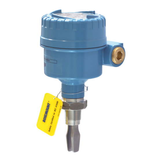
Level switch
Hide thumbs
Also See for Rosemount 2120:
- Reference manual (82 pages) ,
- Quick start manual (36 pages) ,
- Manual supplement (16 pages)

Related Manuals for Emerson Rosemount 2120


Summary of Contents for Emerson Rosemount 2120
- Page 1 Quick Start Guide 00825-0100-4030, Rev GA June 2020 ™ Rosemount 2120 Level Switch Vibrating Fork...
-
Page 2: Table Of Contents
Quick Start Guide June 2020 Contents About this guide...........................3 Installation........................... 5 Prepare the electrical connections....................10 Connect wiring and power-up....................25 Configuration..........................31 Operation...........................33 Servicing and troubleshooting....................34 Rosemount 2120 Level Switch... -
Page 3: About This Guide
June 2020 Quick Start Guide About this guide This Quick Start Guide provides basic guidelines for the Rosemount 2120. Refer to the Rosemount 2120 Reference Manual for more instructions. The manual and this guide are also available electronically at Emerson.com/ Rosemount. - Page 4 Equipment ratings and certifications are no longer valid on any products that have been damaged or modified without the prior written permission of Emerson. Any continued use of product that has been damaged or modified without the written authorization is at the customer’s sole risk and expense.
-
Page 5: Installation
June 2020 Quick Start Guide Installation Fork alignment in a pipe installation Figure 2-1: Correct Fork Alignment for Pipe Installation A. Tri Clamp process connections have a circular notch B. Threaded process connections have a groove Fork alignment in a vessel (tank) installation Figure 2-2: Correct Fork Alignment for Vessel (Tank) Installation A. - Page 6 A gasket may be used as a sealant for BSPP (G) threaded connections. 2.3.2 Threaded vessel (tank) or pipework connection • Vertical installation. Tighten using the hexagon only Gasket for BSPP (G) threaded connection • Horizontal installation. Gasket for BSPP (G) threaded connection Tighten using the hexagon only Rosemount 2120 Level Switch...
- Page 7 June 2020 Quick Start Guide 2.3.3 Threaded flange connection Procedure 1. Place the customer-supplied flange and gasket on the vessel (tank) nozzle. Gasket (customer supplied) 2. Tighten the bolts and nuts with sufficient torque for the flange and gasket. 3. Screw the level switch into the flange thread. Tighten using the hexagon only Gasket for BSPP (G) threaded connection Quick Start Guide...
- Page 8 Quick Start Guide June 2020 Mounting the flanged version Procedure 1. Lower the level switch into the nozzle. Gasket (customer supplied) 2. Tighten the bolts and nuts with sufficient torque for the flange and gasket. Rosemount 2120 Level Switch...
- Page 9 June 2020 Quick Start Guide Mounting the Tri Clamp version Procedure 1. Lower the level switch into the flange face. Seal (supplied with Tri Clamp) 2. Fit the Tri Clamp. Quick Start Guide...
-
Page 10: Prepare The Electrical Connections
8/16 mA electronics: 24 Vdc Hazardous areas When the level switch is installed in hazardous areas (classified locations), local regulations and the conditions-of-use specified in applicable certificates must be observed. Review the Rosemount 2120 Product Certifications document for information. Rosemount 2120 Level Switch... - Page 11 June 2020 Quick Start Guide Wiring diagrams CAUTION • Before use, check the cable glands and blanking plugs are suitably rated. • Isolate supply before connecting the switch or removing the electronics. • The Protective Earth (PE) terminal must be connected to an external earthing system.
- Page 12 Mode: wet on, low level alarm < 4 mA < 4 mA 12 V 12 V Fuse Fuse Fuse Fuse 2A(T) 2A(T) (Ground) (Ground) 2A(T) 2A(T) (Ground) (Ground) DPST DPST DPST DPST = Load on = Load off Rosemount 2120 Level Switch...
- Page 13 June 2020 Quick Start Guide 3.5.2 PNP/PLC electronics cassette Figure 3-2: PNP Output for Load and Direct PLC Switching (Yellow Label) Isolate supply before making connections. Example of external wiring Fuse 2A(T) (Ground) U = 20 - 60 V (dc) 2 3 4 <...
- Page 14 < 3 V (Ground) (Ground) (Ground) (Ground) PNP dc < 3 V < 3 V (Ground) (Ground) (Ground) (Ground) Fuse Fuse Fuse Fuse <100 mA <100 mA 1A(T) 1A(T) 1A(T) 1A(T) = Load on = Load off Rosemount 2120 Level Switch...
- Page 15 A Double Pole, Single Throw on/off switch must be fitted for safe disconnection of the power supply. Fit the DPST switch as near as possible to the Rosemount 2120. Keep the DPST switch free of obstructions. Label the DPST switch to indicate it is the supply disconnection device for the Rosemount 2120.
- Page 16 Mode: dry on, high level alarm Mode: wet on, low level alarm NC C NO NC C NO NC C NO NC C NO NC C NO NC C NO NC C NO NC C NO Rosemount 2120 Level Switch...
- Page 17 A Double Pole, Single Throw on/off switch must be fitted for safe disconnection of the power supply. Fit the DPST switch as near as possible to the Rosemount 2120. Keep the DPST switch free of obstructions. Label the DPST switch to indicate it is the supply disconnection device for the Rosemount 2120.
- Page 18 Mode: dry on, high level alarm Mode: wet on, low level alarm NC C NO NC C NO NC C NO NC C NO NC C NO NC C NO NC C NO NC C NO Rosemount 2120 Level Switch...
- Page 19 FAULT A. A certified intrinsically safe isolating amplifier to IEC 60947-5-6 Note • This cassette is suitable for Intrinsically Safe (IS) applications and requires a certified isolating barrier. See the Rosemount 2120 Product Certifications document for Intrinsically Safe approvals. •...
- Page 20 Quick Start Guide June 2020 Table 3-5: NAMUR Cassette Functions Mode: dry on, high level alarm Mode: wet on, low level alarm > 2.2 mA > 2.2 mA < 1.0 mA < 1.0 mA Rosemount 2120 Level Switch...
- Page 21 FAULT A. A certified intrinsically safe isolating amplifier to IEC 60947-5-6 Note • This cassette is suitable for Intrinsically Safe (IS) applications and requires a certified isolating barrier. See the Rosemount 2120 Product Certifications document for Intrinsically Safe approvals. •...
- Page 22 June 2020 Table 3-6: 8/16 mA Cassette Functions Mode: dry on, high level alarm Mode: wet on, low level alarm > 15 mA < 8.5 mA > 15 mA < 8.5 mA (Ground) (Ground) (Ground) (Ground) Rosemount 2120 Level Switch...
- Page 23 June 2020 Quick Start Guide Grounding Always ground the housing in accordance with national and local electrical codes. 3.6.1 Grounding using the cable shield Make sure the instrument cable shield is: • Trimmed close and insulated from touching the level switch housing. •...
- Page 24 Quick Start Guide June 2020 3.6.2 Grounding the housing of a level switch Figure 3-8: Ground Screws A. External ground screw Rosemount 2120 Level Switch...
-
Page 25: Connect Wiring And Power-Up
The cover must also not to be removed in extreme environmental conditions. • Versions of the Rosemount 2120 with a metal housing are explosion-proof/flameproof. They have a cover-lock to be undone first. - Page 26 Quick Start Guide June 2020 3. Remove the plastic plugs. Versions of the Rosemount 2120 with a glass-filled-nylon housing do not have plastic plugs fitted. 4. Pull cables through the cable gland/conduits. • Cassettes with a single terminal only require one cable.
- Page 27 June 2020 Quick Start Guide 5. Connect the cable wires (see Wiring diagrams for other cassettes). 6. Ensure proper grounding (see Grounding). 7. Tighten the cable glands. Apply PTFE tape or other sealant to the threads. Quick Start Guide...
- Page 28 Make sure to arrange the wiring with a drip loop. 8. Plug and seal the unused conduit connection to avoid moisture and dust accumulation inside the housing. Apply PTFE tape or other sealant to the threads. Rosemount 2120 Level Switch...
- Page 29 June 2020 Quick Start Guide 9. Attach and tighten the cover. Make sure the cover is fully engaged. Required for explosion-proof/flameproof installations only: The cover must be fully engaged to comply with explosion-proof requirements. Quick Start Guide...
- Page 30 Quick Start Guide June 2020 11. Re-lock the cover. 12. Connect the power supply. Rosemount 2120 Level Switch...
-
Page 31: Configuration
June 2020 Quick Start Guide Configuration Set the mode and time delay for the output All electronics cassettes have a rotating switch for setting the electrical output to be on when the fork is sufficiently dry ("Dry On") or when the fork is sufficiently wet ("Wet On"). - Page 32 Wet On Seconds Delay A. Mode “Dry On” and 1 second time delay Figure 5-3: Typical Settings for Low Level Applications Dry On Wet On Seconds Delay A. Mode “Dry On” and 1 second time delay Rosemount 2120 Level Switch...
-
Page 33: Operation
1 every 4 seconds Load fault; load current too high; load short circuit 2 times / second Indication of successful calibration 3 times / second Contact Emerson to report an internal PCB fault is being indicated. Problem (e.g. supply) Quick Start Guide... -
Page 34: Servicing And Troubleshooting
A magnetic test point is marked on the side of the housing to allow a functional test of the Rosemount 2120 in the overall system. By touching a magnet to the target, the output from the level switch will change state while the magnet is present. - Page 35 June 2020 Quick Start Guide Spare parts See the Rosemount 2120 Product Data Sheet for the latest information about spare parts. Replacement and calibration of cassettes When replacing a damaged or faulty electronics cassette, it is necessary to calibrate the replacement cassette to the operating frequency of the fork sensor.
- Page 36 Set a longer switching time delay. Excessive electrical noise. • Suppress the cause of the interference. Cassette has been fitted from • Fit the factory supplied another Rosemount 2120. cassette and then calibrate. (See Replacement and calibration of cassettes). Rosemount 2120 Level Switch...
- Page 37 June 2020 Quick Start Guide Quick Start Guide...
- Page 38 Quick Start Guide June 2020 Rosemount 2120 Level Switch...
- Page 39 June 2020 Quick Start Guide Quick Start Guide...
- Page 40 The Emerson logo is a Twitter.com/Rosemount_News trademark and service mark of Emerson Electric Facebook.com/Rosemount Co. Rosemount is a mark of one of the Emerson Youtube.com/user/ family of companies. All other marks are the RosemountMeasurement property of their respective owners.
Need help?
Do you have a question about the Rosemount 2120 and is the answer not in the manual?
Questions and answers