Emerson Rosemount 2130 Functional Safety Manual
Level switch
Hide thumbs
Also See for Rosemount 2130:
- Reference manual (78 pages) ,
- Quick start manual (41 pages) ,
- Quick start manual (40 pages)
Table of Contents
Advertisement
Quick Links
Download this manual
See also:
Reference Manual
Advertisement
Table of Contents

Related Manuals for Emerson Rosemount 2130


Summary of Contents for Emerson Rosemount 2130
- Page 1 Manual Supplement 00809-0500-4130, Rev AG March 2015 Rosemount 2130 Functional Safety Manual...
-
Page 3: Table Of Contents
Ordering information ........... 6 3Section 3: Designing a Safety Function using the Rosemount 2130 Safety function . - Page 4 Manual Supplement Contents 00809-0500-4130, Rev AG March 2015 6Appendix A: Specifications General ............. .15 Useful life.
-
Page 5: Scope And Purpose Of The Safety Manual
2130 level switch when showing compliance with the IEC 61508 or IEC 61511 functional safety standards. It indicates all assumptions that have been made on the usage of the Level Switch. If these assumptions cannot be met by the application, the SIL capability of the Rosemount 2130 may be adversely affected. - Page 6 Manual Supplement Section 1: Introduction 00809-0500-4130, Rev AG March 2015 Fail Dangerous Undetected Failure that is dangerous and that is not detected. Fail No Effect Failure of a component that is part of the safety function but that has no effect on the safety function.
-
Page 7: Documentation And Standards
Electrical/Electronic/Programmable Electronic Safety-Related Systems MOB 08/08-57 R005 FMEDA Report Version V1, Revision R5 for the Rosemount 2130 Level Switch 00813-0100-4130 Rosemount 2130 Product Data Sheet 00809-0100-4130 Rosemount 2130 Reference Manual Table 1-2. Associated Standards Standards Purpose of Standards IEC 61508: 2000... - Page 8 Manual Supplement Section 1: Introduction 00809-0500-4130, Rev AG March 2015 Introduction...
-
Page 9: 2Section 2: Product Description
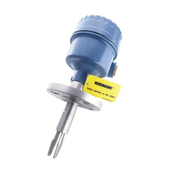
Product Description Operation principle The Rosemount 2130 level switch consists of a tuned fork with a driver and receiver element, and integral interface electronics. The 2130 level switch is based on the principle that the resonant frequency of a tuned fork changes when it is immersed in a liquid. The frequency change is detected and used to switch an electronic output. -
Page 10: Ordering Information
Manual Supplement Section 2: Product Description 00809-0500-4130, Rev AG March 2015 Ordering information Typical Model Number: 2130 L A 2 E S 9 NN B A 0000 1 NA QT The first option code after “2130” indicates the output type: L = Direct Load Switching (Mains two-wire) ... -
Page 11: Safety Function
Rosemount 2130 Safety function A change in liquid level through the switch point of the Rosemount 2130 level switch causes it to operate. It may be used in high level or low level safety related applications. It is important that the 2130 is user-configured for the correct application. -
Page 12: Sil Capability
Each subsystem must be checked to assure compliance with minimum Hardware Fault Tolerance (HFT) requirements. When using the Rosemount 2130 level switch in a redundant configuration, a common cause factor of at least 5% should be included in the safety integrity calculations. -
Page 13: Connection Of The 2130 To The Sis Logic Solver
FMEDA report (and this safety manual). Connection of the 2130 to the SIS logic solver The Rosemount 2130 level switch should be connected to the safety-rated logic solver which is actively performing the safety function as well as automatic diagnostics (if any) designed to diagnose potentially dangerous failures within the level switch. - Page 14 Manual Supplement Section 3: Designing a Safety Function using the Rosemount 2130 00809-0500-4130, Rev AG March 2015 Personnel performing maintenance and testing on the 2130 level switch shall first be assessed as being competent to do so Results from periodic proof tests shall be recorded and periodically reviewed ...
-
Page 15: 4Section 4: Installation And Commissioning
For all product information and documentation downloads, see the on-line Rosemount 2130 web page at www.rosemount.com. Installation The Rosemount 2130 level switch must be installed as described in the installation section of the product reference manual. Check that environmental conditions do not exceed the ratings in the specification section. -
Page 16: Output Mode Setting
00809-0500-4130, Rev AG March 2015 4.4.2 Output mode setting The Rosemount 2130 level switch must be user-configured for an application so that the output is ON in the Safe or Normal condition (see Table 4-1). The response time (seconds delay) may be set to a convenient value to prevent trips that are spurious i.e. -
Page 17: 5Section 5: Operation And Maintenance
Repair procedures in the Rosemount 2130 level switch reference manual must be followed. Notification of failures In case of malfunction of the system or SIF, the Rosemount 2130 level switch shall be put out of operation and the process shall be kept in a safe state by other measures. - Page 18 Manual Supplement Section 5: Operation and Maintenance 00809-0500-4130, Rev AG March 2015 Operation and Maintenance...
-
Page 19: 6Appendix A: Specifications
Based on general field failure data and manufactures component data, a useful life period of approximately 18 years is expected for the Rosemount 2130 level switch at an ambient temperature of 55 °C. This decreases by a factor of two for every increase of 10 °C, and increases by a factor of two for every decrease of 10 °C. -
Page 20: Useful Lifetime
It is the responsibility of the end-user to maintain and operate the Rosemount 2130 level switch according to the manufacturer's instructions. Furthermore, regular inspection should show that all components are clean and free from damage. -
Page 21: 7Appendix B: Proposed Proof-Test Procedure
Manual Supplement Appendix B: Proposed Proof-test Procedure March 2015 00809-0500-4130, Rev AG Appendix B Proposed Proof-test Procedure Suggested proof-test According to Section 7.4.3.2.2 (f) of the standard IEC 61508-2, proof-tests shall be undertaken to reveal dangerous faults which are undetected by diagnostic tests. This means that it is necessary to specify how dangerous undetected faults which have been noted during the Failure Modes, Effects, and Diagnostic Analysis can be detected during proof-testing. - Page 22 Manual Supplement Appendix B: Proposed Proof-test Procedure 00809-0500-4130, Rev AG March 2015 Proposed Proof-test Procedure...
-
Page 23: 8Appendix C: Product Identification
Manual Supplement Appendix C: Product Identification March 2015 00809-0500-4130, Rev AG Appendix C Product Identification Approved cassette part numbers Table C-1 shows the part numbers of the electronic cassettes approved to IEC61508:2000. Table C-1. IEC61508:2000 approved cassette numbers Output Type Part Numbers of Electronic Cassettes NAMUR (Code N) 02130-1060-0001... - Page 24 Manual Supplement Appendix C: Product Identification 00809-0500-4130, Rev AG March 2015 Product Identification...
- Page 26 Standard Terms and Conditions of Sale can be found at: Jebel Ali Free Zone - South 2 www.rosemount.com\terms_of_sale. The Emerson logo is a trademark and service mark of Emerson Electric Co. Dubai, United Arab Emirates Rosemount and Rosemount logotype are registered trademarks of Rosemount Inc.
Need help?
Do you have a question about the Rosemount 2130 and is the answer not in the manual?
Questions and answers