
Related Manuals for BIO-MED DEVICES IC-2A


Summary of Contents for BIO-MED DEVICES IC-2A
- Page 1 BIO-MED DEVICES IC-2A ADULT INTENSIVE CARE VENTILATOR SERVICE MANUAL CATALOG #8011A PRICE $35.00 REV. 122606 BIO-MED DEVICES, INC. 61 SOUNDVIEW ROAD, GUILFORD, CT 06437 (203) 458-0202 www.biomeddevices.com...
-
Page 2: Table Of Contents
WARNING, CAUTIONS, AND NOTES ................3 WARNINGS......................... 3 CAUTIONS ........................4 NOTES ........................4 DESCRIPTION......................8 INTRODUCING THE IC-2A VENTILATOR..............8 Controls, Indicators and Connectors................8 Modes of Operation ..................... 9 SPECIFICATIONS AND LIMITATIONS............... 9 FUNCTIONAL DESCRIPTION ................11 OPERATING MODES ....................11 LOGIC GATE...................... -
Page 3: Warranty
(1) year from the date of purchase. BIO-MED DEVICES, INC. will repair or, at its option, replace any part or all of this Ventilator which fails to conform to this warranty at no cost to the purchaser FOR MATERIALS AND LABOR. - Page 4 IC-2A Ventilator and provide specific maintenance and service instructions. A complete Table of Contents, List of Illustrations, and List of Tables are included to help...
-
Page 5: Warning, Cautions And Notes
Ventilator back on, in order to avoid erroneous breaths and possible harm to the patient. • It is essential, with the triggered demand flow of the IC-2A, that the inspiratory effort be properly adjusted to assure that the patient can obtain gas. -
Page 6: Cautions
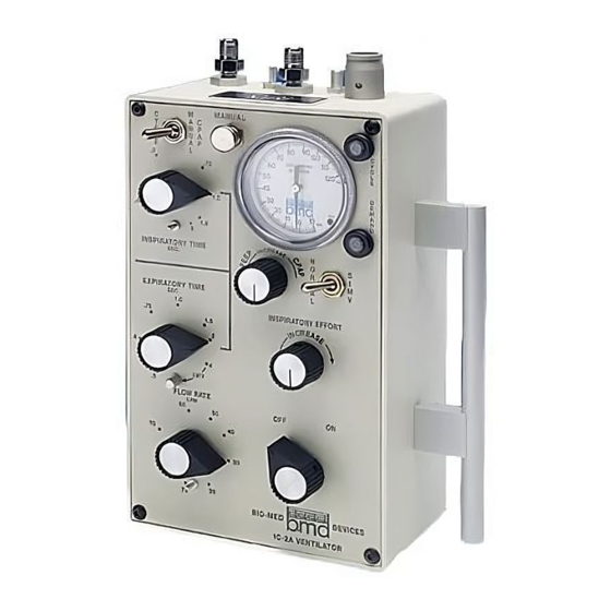
• Any intensive care ventilator circuit may be used with the IC-2A Ventilator including a configuration using both inspiratory and expiratory hoses. exhalation valve may be used. It should be noted that the IC-2A is supplied with a patient circuit (part number 8002A). - Page 7 FIG. 1-1 IC-2A Ventilator...
- Page 8 PHYSICIAN. BEFORE OPERATING THIS INSTRUMENT, READ THE INSTRUCTION MANUAL THOROUGHLY. PARTICULAR ATTENTION SHO ULD BE GIVEN TO THE USE OF THE DEMAND MODE. DATE OF M FR. 0086 BIO−MED DEVICES, INC. GUILFORD, CT U.S.A. FIG. 1-2 IC-2A Ventilator (Rear View)
- Page 9 SYMBOLS AND ABBREVIATIONS Special symbols and abbreviations are used in this manual and are listed here to provide an easy reference for maintenance personnel. SYMBOL/ABBREVIATION DEFINITION Orifice, Resistor, or Restrictor Variable Orifice, Variable Resistor, Variable Restrictor, or Needle Valve Volume Capacitor Regulated Gas Supply Logic Gate Pressure Regulator...
-
Page 10: Description
The IC-2A Ventilator (Figure 1-1) is a highly sophisticated, precision, pneumatic, life support device, built to rigid specifications. The IC-2A Ventilator is designed for respiratory support of adult patients both in a health-care facility and during transport. It can be operated within volume or pressure limits and has a wide range of inspiratory/expiratory time ratios (I/E). -
Page 11: Modes Of Operation
DEMAND indicator Activates to indicate any cycle initiated by patient breathing effort or backup timer Table 1-2. IC-2A Ventilator – Top and Back Panel Controls and Connectors Control or Indicator Function Max. Pressure Control Rotary control for setting upper pressure limit for each cycle... - Page 12 *INSPIRATORY and EXPIRATORY TIME controls are calibrated at sea level and 20°C using USP oxygen. Changes in barometric pressure, altitude changes, or use of diluted oxygen will affect time calibration. Table 1-3. IC-2A Specifications and Limitations (continues) Specification/Limitation Range Rate...
-
Page 13: Functional Description
FUNCTIONAL DESCRIPTION INTRODUCTION Figure 2-1 presents a schematic view of the IC-2A Ventilator. Figure 2-2 presents the logic system. Refer to the list of symbols and abbreviations at the front of the manual. OPERATING MODES Intermittent Positive Pressure Ventilation (IPPV) In the IPPV mode the IC-2A Ventilator acts as a controller or assist/controller. - Page 14 Fig. 2-1 IC-2A Schematic Diagram LEGEND Pressure Gauge Line Connector Pressure Gauge Flow Rate Control Valve (panel control) OFF/ON Control Valve (panel control) Patient Hose Connector Logic Gas Supply 100% O2 Connector Exhalation Valve Line Connector Patient Gas Supply Connector...
- Page 15 Fig. 2-2 IC-2A System Logic Diagram LEGEND CYCLE/MANUAL CPAP Toggle Valve (panel switch) MANUAL Button CYCLE Indicator Inspiratory Time Needle Valve (panel control) Demand Indicator PEEP/CPAP Needle Valve (panel control) NORMAL/SIMV Toggle Valve (panel switch) Expiratory Time Needle Valve (panel control)
- Page 16 With this triggered demand flow system, it is only necessary to trigger the unit initially. The IC-2A then provides a bolus of gas equal to the inspiratory time multiplied by the flow rate.
-
Page 17: Logic Gate
When the CYCLE/MAUAL CPAP switch is placed in the MANUAL CPAP position, the function of the IC-2A Ventilator is very similar to the SIMV mode. In the CPAP mode, and inspiratory effort triggers the flow if a volume of gas equal to inspiratory time multiplied by flow rate. - Page 18 The five Logic Gate ports are generally used as follows: Ports 1 and 2 Switching Signals Port 3 Output Signal Ports 4 and 5 Supply or Exhaust Pressure to Ports 1 and 2 actuate a diaphragm assembly allowing either Port 4 or 5 to connect with Port 3.
-
Page 19: Installation And Operation
If the IC-2A was shipped directly to you and damage due to shipment is found, notify the carrier at once. Only you, the consignee, can make a claim against the carrier for damage in shipment. - Page 20 The IC-2A will operate with a supply pressure outside of the 50 ±5 psi range, but the accuracy of the settings may be impaired. WARNING: In no case should a supply pressure less than 35 or over...
-
Page 21: Ic-2A Ventilator Set-Up
PEEP pressure attainable, depending on the area ratios of the exhalation valve used. IC-2A FINAL CHECKOUT Before connecting the IC-2A Ventilator to a patient perform the following checks to ensure that the Ventilator is at its optimum operating condition. - Page 22 Positive Pressure Breathing with Demand Triggering Check a. Connect a patient circuit to the Ventilator and set the controls/switches as follows: 1. INSPIRATORY TIME to 1 second 2. EXPIRATORY TIME to 2 seconds 3. FLOW RATE to 30 lpm 4. MAX. PRESSURE fully counterclockwise 5.
- Page 23 Continuous Positive Airway Pressure (CPAP) Check a. Connect a test lung to the patient circuit output and set the control as follows: 1. FLOW RATE to 30 LPM 2. PEEP/CPAP fully clockwise 3. MAX PRESSURE fully counterclockwise 4. INSPIRATORY EFFORT anywhere except so as to cause auto-cycling 5.
- Page 24 b. Ventilator should cycle only on patient demand or when triggered by the back- up timer. Exhalation valve should only pressurize during an inspiratory period (after the set expiratory or back-up timer period has elapsed). c. Set the EXPIRATORY TIME control to the “I” in IMV. Trigger the Ventilator and let the expiratory period elapse.
-
Page 25: Operating Procedure
Tidal volume (expressed in milliliters) is the product of inspiratory time (seconds) and flow rate (milliliters per second): TIDAL VOLUME (ml) = INSPIRATORY TIME (sec) X FLOW RATE (ml/sec) Figures 3-1 and 3-2 are printed on the side of the IC-2A for the convenience of operating personnel. - Page 26 RATE & I/E RATIO INSPIRATORY TIME (SEC.) 1.00 1.50 2.00 1:1.3 1.5:1 1:1.5 1:1.2 1.3:1 1.7:1 2.5:1 3.3:1 1:1.9 1:1.5 1.3:1 2.7:1 1.00 1:2.5 1:1.3 1.5:1 1.50 1:3.8 1:1.5 1.3:1 2.00 1:2.7 1:1.3 4.00 1:10 1:5.3 1:2.7 Fig. 3-1 TIDAL VOLUME INSPIRATORY TIME (SEC.) 1.00 1.50...
- Page 27 Adjust MAX. PRESSURE control to a level 5 to 10 cmH 0 above that reached with patient connected. Re-connect patient airway to Y-connection. The IC-2A is now limited to the tidal volume set, but maximum pressure is limited in the event of changes in resistance or compliance.
- Page 28 It should be set with the particular flow rate used. The IC-2A Ventilator will now be limited to the pressure set. When operating in this mode, the exact tidal volume is unknown, since gas is vented to the atmosphere through the exhalation valve as soon as the preset pressure limit is reached during each inspiration.
- Page 29 DEMAND and CYCLE indicators together indicate an assisted breath or a backup breath. Continuous Positive Airway Pressure (CPAP) WARNING: Whenever the IC-2A Ventilator is turned off, disconnect the patient before turning the Ventilator back on, in order to avoid erroneous breaths and possible harm to the patient.
- Page 30 c. Set desired flow rate and inspiratory time. d. Set Max. Pressure control level (real panel control) by occluding patient port, pressing MANUAL button, and adjusting maximum pressure. e. Adjust PEEP level in manner similar to maximum pressure, if it is desired to have PEEP during manual cycles.
-
Page 31: Maintenance Instructions
WARNING: Because this is a CE marked device, it must never be modified without prior expressed written consent from Bio-Med Devices. The IC-2A Ventilator requires very little maintenance. It should be protected from abusive mechanical shock and kept in a clean condition. - Page 32 A new flat may have to be filed on the brass bushing threads in order to install in earlier style panels. g. Replace the control knobs. h. When all the preventative maintenance replacement procedures have been completed, the IC-2A Ventilator must be tested and recalibrate. Refer to Section 5.
-
Page 33: Testing And Calibration
TESTING AND CALIBRATION INTRODUCTION Perform testing and calibration on the IC-2A Ventilator whenever a component has been replaced, after preventative maintenance, and whenever the operator suspects a component is not operating within specifications. The following tests and calibrations are included in this section: a. -
Page 34: Fail-Safe Cutoff Valve Calibration
(listed in order of importance): a. Cutoff pressure is as close to 30 psi as possible without exceeding it. b. Delay in delivery of a full and immediate bolus of gas when the IC-2A Ventilator is turned on is as short as possible. -
Page 35: Demand Circuit Calibration
A vacuum of 0.5 cmH O or less, applied to the patient breathing circuit, should trigger the IC-2A Ventilator into an inspiratory cycle. With maximum PEEP or CPAP applied, no more than a 2 cmH O vacuum should be necessary to trigger the ventilator. - Page 36 4. Disconnect the test gauge and re-connect the brown tubing to the T- connector. Use the longer tubing if line must be bent to connect. c. While the IC-2A Ventilator is auto-cycling, increase the inspiratory effort to the point where it just stops auto-cycling.
-
Page 37: Maximum Pressure Calibration
maximum PEEP/CPAP pressure should be needed to trigger the Ventilator. If a larger differential is needed to trigger the Ventilator, replace the demand valve (item 10). CAUTION: Do not attempt to repair the demand. Its assembly is highly critical and must be performed at the factory. MAXIMUM PRESSURE CALIBRATION The maximum pressure circuit consists of the maximum pressure needle valve (item 19), the yellow and violet maximum pressure resistor line (yellow and violet tubing), and... -
Page 38: Peep/Cpap Calibration
PEEP/CPAP CALIBRATION As the PEEP/CPAP control is turned counterclockwise a positive pressure is applied to the exhalation valve. This induces a positive pressure in the patient circuit during the expiratory period. A regular breath without any PEEP pressure starts out with an inspiratory period and the pressure in the patient circuit can increase to the pressure set by the MAX. -
Page 39: Timing Calibration
Setting the PEEP/CPAP pressure for exactly 25 cmH O while the CYCL/MANUAL CPAP switch is in the MANUAL CPAP position generally keeps the PEEP/CPAP pressure in the 25 ±5 cmH O range when the CYCLE/MANUAL CPAP switch is set to CYCLE. -
Page 40: Flow Rate Calibration
g. Adjusting the knob position will also affect the timing on a non-linear scale with the greatest effect at 2.0 and the least at .4. When resetting the control knob on the shaft make sure the knob is free to rotate from stop to stop without bottoming out on the top of the valve and is not able to pass over the stop. -
Page 41: Pressure Gauge Calibration
PRESSURE GAUGE CALIBRATION The Pressure Gauge readings can be compared to a standard by teeing into the hose connected to the PRESSURE GAUGE fitting to the IC-2A Ventilator and connecting it to the standard gauge. To zero the Pressure Gauge: a. -
Page 42: Parts Lists
PARTS LISTS INTRODUCTION Figure 6-1 shows the internal view of the IC-2A Ventilator with rear panel removed. Table 6-1 is a parts list referenced to the index numbers in Figures 6-1. Table 6-2 is referenced by part number. 23 2 1... - Page 43 PATIENT LOGIC GAS PATIENT GAS SUPPLY SUPPLY HOSE 100% O AIR/OXYGEN 50±5 PSI 50±5 PSI 345±34.5 kPa 345±34.5 kPa 30 LPM MAX. FLOW 82 LPM MAX. FLOW MAX. PRESSURE PRESSURE EXHALATION GAUGE VALVE CAUTION: THE CIRCUIT W ILL NOT PRESS URIZE WITH THIS KNO B AT THE FULL CW POSITIO N.
- Page 44 Table 6-1 IC-2A Parts List INDEX PART PART NO. CYCLE/MANUAL CPAP toggle valve PRT1705 MANUAL button PRT1706 CYCLE indicator PRT1708 INSPIRATORY TIME needle valve PRT1104 Pressure Gauge PRT1013 DEMAND indicator PRT1708 PEEP/CPAP needle valve PRT1105 NORMAL/SIMV toggle valve PRT1707 EXPIRATORY TIME needle valve...
- Page 45 Expiratory time capacitor test port PRT1131 Expiratory time capacitor PRT1103 Patient gas supply input hose PRT1118 Logic gas supply input hose PRT1118 Patient output tube PRT1118 Patient circuit manifold PRT1702 Feedback resistor PRT1141A Backup timer resistor PRT1142A Delay line capacitor and delay line PRT1153 Backup timer capacitor PRT1102...
- Page 46 Feedback resistor line (includes variable resistor) PRT1142A Backup timer resistor PRT1153 Delay line (includes capacitor) PRT1203 Round knobs PRT1204 Pointed knobs PRT1220 IC-2A case PRT1221A Front panel PRT1222 Rear panel PRT1223 Handle PRT1301 3/8” X 10-32 button head cap screws (panels) PRT1400...
- Page 47 PRT1705A CYCLE/MANUAL CPAP toggle valve PRT1706 Manual valve PRT1707 NORMAL/SIMV toggle valve PRT1708 Indicator PRT1709 OFF/ON valve PRT1710 FLOW RATE control valve PRT1711 Logic gas supply connector assembly PRT1712 Patient gas supply connector assembly PRT1713 Logic supply filter PRT1714 Pilot valve 2013A Universal mounting bracket (male) 8004...
Need help?
Do you have a question about the IC-2A and is the answer not in the manual?
Questions and answers