Table of Contents

Related Manuals for BIO-MED DEVICES IC-2A

Summary of Contents for BIO-MED DEVICES IC-2A
- Page 1 BIO-MED DEVICES IC-2A ADULT INTENSIVE CARE VENTILATOR INSTRUCTION MANUAL CATALOG #8050A PRICE $25.00 REV 122606 BIO-MED DEVICES, INC. 61 SOUNDVIEW ROAD, GUILFORD, CT 06437 (203) 458-0202 Fax (203) 458-0440 www.biomeddevices.com...
-
Page 2: Table Of Contents
TABLE OF CONTENTS ADDENDUMS ........................1 MAGNETIC RESONANCE IMAGING ENVIRONMENT ..........1 SYMBOL EXPLANATION...................1 IC-2A WITH TOP MOUNTED BLENDER..............2 BLENDER SETUP INSTRUCTIONS WITH HEAVY DUTY STAND......3 UNPACKING........................6 WARRANTY........................8 WARNINGS ........................9 CAUTIONS........................9 I. GENERAL........................11 A. INTENDED USE ....................11 B. MODES OF OPERATION ...................11 C. -
Page 3: Addendums
MAGNETIC RESONANCE IMAGING ENVIRONMENT WARNING: ONLY AN IC-2A ORIGINALLY MANUFACTURED BY BIO-MED DEVICES FOR MRI USE OR RECEIVING AN MRI CONVERSION BY BIO-MED DEVICES IS TO BE USED IN AN MRI ENVIRONMENT. THESE UNITS WILL BE DESIGNATED BY AN MRI LABEL AND AN “M”... -
Page 4: Ic-2A With Top Mounted Blender
IC-2A WITH TOP MOUNTED BLENDER The following instructions explain how to make the connections between your IC-2A and blender using the Bio-Med Blender Hose Kit, catalog #2005IC. 1. Mount the blender to the IC-2A using the nut to nut coupler (D) – (blender primary outlet to IC-2A patient supply). -
Page 5: Blender Setup Instructions With Heavy Duty Stand
The high pressure wye is to be used to split your oxygen source before the blender so the short leg goes to the blender input and the long leg goes to the IC-2A logic input. Connect one end of a 2' oxygen supply hose to the input of this wye and the other end to the output fitting on the oxygen cylinder regulator. - Page 6 Connect the short hose leg of the wye to the blender oxygen input . Connect the long hose leg of the wye to the elbow on the IC-2A logic supply input. Connect the 10' air supply hose to the blender air input.
-
Page 8: Unpacking
If the IC-2A was shipped directly to you and damage due to shipment is found, notify the carrier at once. Only you, the consignee, can make a claim against the carrier for damage in shipment. - Page 9 MLAB024 WARRANTY CARD 2005ICHC HOSE KIT FOR 8001AMBC (see below) 2005ICHC HOSE KIT INCLUDES THE FOLLOWING: CAT. # DESCRIPTION PFIT143 SUPPLY ELBOW ADAPTERS 8005BH HIGH PRESSURE WYE FOR BLENDER ON STAND 1010-2 2' OXYGEN SUPPLY HOSE 1010 10’ OXYGEN SUPPLY HOSE 1011-2 2’...
-
Page 10: Warranty
WARRANTY The IC-2A Ventilator is warranted to be free from defects in workmanship and material for one (1) year from the date of purchase. To insure its performance is maintained, any repair during this warranty period must be performed by BMD. -
Page 11: Warnings
Do not re-use disposable breathing circuits. Do not use in a MRI room unless the IC-2A has been built by Bio-Med Devices for such an environment. This will be indicated by a MRI plaque on the top of the unit and a “M” at the end of the serial NUMBER. - Page 12 Always turn on the IC-2A before attaching to patient to avoid erroneous breaths. Whenever the IC-2A is turned off, disconnect the patient before turning the ventilator back on in order to avoid erroneous breaths. Antistatic or electrically conductive hoses or tubing should not be used.
-
Page 13: General
I\E ratios less than or greater that 1:1. WARNING: Do not use in a MRI room unless the IC-2A has been built by Bio-Med Devices for such an environment. This will be indicated by a MRI plaque on the top of the unit and a “M”... - Page 14 Oxygen concentration is varied by the use of an external accessory blender or premixed gas supply. Care should be taken to select a blender capable of maintaining constant supply pressure over the full range of flow rates that the IC-2A provides. As with all ventilation systems, the O concentration should be tested periodically with an oxygen analyzer.
-
Page 15: Description
IPPV With the CYCLE/CPAP-MANUAL selector set in cycle and NORMAL/SIMV selector set in normal, the IC-2A acts as a controller or assist/controller. A pilot valve operated by the timing signal from the fluid logic opens for a preset length of time (Insp. Time) allowing gas to flow at some rate established by the flow rate control. - Page 16 Whenever the PEEP/CPAP level is changed, the inspiratory effort control should be readjusted. Continuous Positive Airway Pressure (CPAP) When the CYCLE/CPAP selector switch is placed in the CPAP-MANUAL position the function of the IC-2A is very similar to the SIMV mode. In the...
-
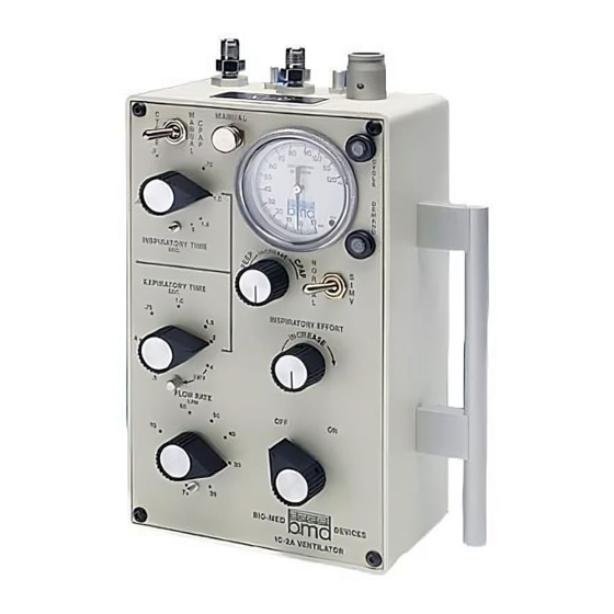
Page 17: Controls, Indicators And Connections
CPAP mode, an inspiratory effort triggers the flow of a volume of gas equal to inspiratory time X flow rate. However, in this mode the high pressure is not applied intermittently to the exhalation valve. Only the PEEP/CPAP control is operative. The PEEP/CPAP control may be turned fully clockwise thus applying zero pressure to the exhalation valve. - Page 18 seconds (may be set to 45 seconds or more in IMV range). Flow rate Sets inspiratory flow rate. Calibrated from 0 to 75 LPM. Inspiratory Effort Adjusts the patient trigger sensitivity. PEEP/CPAP Sets PEEP level when cycle selector switch is in the CYCLE position or CPAP level when switch is set to CPAP.
-
Page 19: Specifications
Variable from 0 to 120 ±20 cmH Maximum Pressure Setting: O. This is dependent upon the type of exhalation valve used. The IC-2A is calibrated using the Bio-Med Devices disposable patient circuit and exhalation valve, Part #8002A. O; ±3% full-scale accuracy. -
Page 20: Installation Considerations
The IC-2A will operate with a supply pressure outside of the 50 ±5 psi (345 ±34.5 kPa ) range, but accuracy of settings may be impaired. IN NO CASE SHOULD A... - Page 21 M-1) may be connected to the pressure gauge line or main patient hose. IT MUST ALWAYS BE USED WHENEVER THE IC-2A IS USED UNATTENDED. Rate-I/E Ratio Monitor--(such as the Bio-Med Devices M-10) may be connected if desired, to simplify use of the ventilator by supplying readout of rate and I/E ratio. It should be connected in the same way as the high/low pressure alarm.
-
Page 22: Set Up
Any intensive care ventilator circuit can be used with the IC-2A including a configuration utilizing both inspiratory and expiratory hoses. Any exhalation valve may be used. It should be noted that the IC-2A is supplied with the Bio-Med Devices patient circuit, catalog #8002A. The maximum pressure limit and maximum PEEP pressure are calibrated using this exhalation valve. -
Page 23: Selection Of Ventilation Parameters And Adjustment Of Controls
V. SELECTION OF VENTILATION PARAMETERS AND ADJUSTMENT OF CONTROLS A. INTERMITTENT POSITIVE PRESSURE VENTILATION (IPPV) WITH OR WITHOUT PEEP Determine and note patient requirements for respiratory rate, I/E ratio and tidal volume. Refer to Table I to find inspiratory time (T ) and expiratory time (T ). -
Page 24: Synchronized Intermittent Mandatory Ventilation (Simv)
Re-connect the patient airway to the WYE. The IC-2A will now be limited to the tidal volume set, but maximum pressure will be limited in the event of changes in resistance or compliance. b) For pressure-limited operation: Adjust MAX. -
Page 25: Continuous Positive Airway Pressure (Cpap)
C. CONTINUOUS POSITIVE AIRWAY PRESSURE (CPAP) NOTE: WHENEVER THE IC-2A IS TURNED OFF, DISCONNECT THE PATIENT BEFORE TURNING THE VENTILATOR BACK ON, IN ORDER TO AVOID ERRONEOUS BREATHS. THE MAXIMUM PRESSURE CONTROL MUST BE TURNED OFF (FULLY CLOCKWISE) IN THE CPAP MODE. -
Page 26: Manual Cycling
NOTE THAT IT IS ESSENTIAL WITH THE TRIGGERED DEMAND FLOW OF THE IC-2A, THAT THE INSPIRATORY EFFORT BE PROPERLY ADJUSTED TO ASSURE THAT THE PATIENT CAN OBTAIN GAS. As in the SIMV mode, no external constant flow source is necessary. -
Page 27: Precautions
• To assure that operation will be trouble-free, attention should be given to the following points: • ALWAYS TEST THE IC-2A EACH TIME BEFORE ATTACHING TO A PATIENT. • All hoses should be securely fastened to fittings. Hand-tighten to avoid damage to fittings. - Page 28 IC-2A. • Do not lean on or place excessive weight on the IC-2A while it is mounted on a bracket since the bracket is designed to support only the IC-2A.
-
Page 29: Maintenance
The IC-2A Ventilator requires very little maintenance. It should be protected from abusive mechanical shock and kept in a clean condition. The IC-2A should only be cleaned by wiping the outside surfaces with alcohol applied to a tissue or cloth. It should never be sprayed with or immersed in any other liquid. - Page 30 PILOT VALVE BLEED With both supplies on, place your ear near back of case. An audible internal leak is normal. PILOT VALVE SEAL With both supplies pressurized and ON/OFF valve to OFF, occlude the circuit exhalation valve exhaust port and observe the manometer on the unit. There should be no continuous rise in pressure indicated by manometer.
- Page 31 PEEP ZERO Set ON/OFF switch to ON. Observe manometer. No pressure should be indicated during the expiratory phase. INSPIRATORY EFFORT Remove occlusion from patient end of circuit. Set ON/OFF switch to ON. With 15 ±5 cm of negative pressure applied to the patient circuit, the DEMAND INDICATOR should activate and the unit should trigger (initiate a breath).
-
Page 32: Calibration
Med Devices for repair. The pressure gauge readings can be compared to a standard by teeing into the hose connected to the GAUGE fitting of the IC-2A, and connecting it to the standard gauge. Should the gauge need zeroing, this may be accomplished while the instrument is inoperative by removing the gauge’s lens and setting the zero screw adjust on the... -
Page 33: Rate & I/E Ratio
TABLE I RATE & I/E RATIO INSPIRATORY TIME (SEC.) 1.00 1.50 2.00 1:1.3 1.5:1 1:1.5 1:1.2 1.3:1 1.7:1 2.5:1 3.3:1 1:1.9 1:1.5 1.3:1 2.7:1 1.00 1:2.5 1:1.3 1.5:1 1.50 1:3.8 1:1.5 1.3:1 2.00 1:2.7 1:1.3 4.00 1:10 1:5.3 1:2.7 RESPIRATORY RATE= (INSP. -
Page 34: Tidal Volume
TABLE II TIDAL VOLUME INSPIRATORY TIME (SEC.) 1.00 1.50 2.00 1000 1000 1330 1250 1670 1000 1500 2000 1170 1750 2330 1250 1880 2500 TIDAL VOLUME (ml.) = INSP. TIME X FLOW RATE (ml/sec.) -
Page 35: European Agent
APPENDIX A EUROPEAN AGENT Bio-Med Devices’ Official Agent in Europe is: HORST HÖRNLA H + H Intermed Schwedenstraße 32 87463 Dietmannsried-Reicholzried United Germany Telefon: (08 31) 6 31 86 Fax: (08 31) 6 09 54... -
Page 36: Mri Test
APPENDIX B MRI TEST The Bio-Med Devices IC-2A MRI ventilator was tested approximately 2 ½ feet inside the bore of a 1.5 tesla MRI unit at which point the magnetic field was estimated to be 13,000 gauss. The results of the test were as follows: 1.
Need help?
Do you have a question about the IC-2A and is the answer not in the manual?
Questions and answers