
Related Manuals for BIO-MED DEVICES MVP-10


Summary of Contents for BIO-MED DEVICES MVP-10
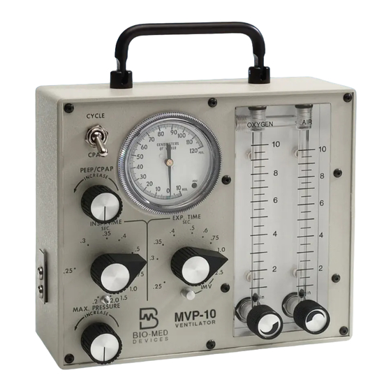
- Page 1 BIO-MED DEVICES MVP-10 NEONATAL/PEDIATRIC VENTILATOR INSTRUCTION MANUAL Catalog #2050 Rev. 042916 BIO-MED DEVICES INC. 61 SOUNDVIEW ROAD, GUILFORD, CT 06437 (800) 224-6633 FAX 203-458-0440 www.biomeddevices.com...
-
Page 3: Table Of Contents
TABLE OF CONTENTS Addendum MAGNETIC RESONANCE IMAGING ENVIRONMENT SYMBOL EXPLANATION UNPACKING STANDARD MVP-10 MVP-10 MRI COMPLETE PACKAGE WARRANTY WARNINGS CAUTIONS I. GENERAL A. INTENDED USE B. MODES OF OPERATION C. FEATURES D. PERFORMANCE CHARACTERISTICS II. DESCRIPTION A. PRINCIPLES OF OPERATION B. -
Page 4: Addendum
MAGNETIC RESONANCE IMAGING ENVIRONMENT WARNING: ONLY AN MVP-10/MRI ORIGINALLY MANUFACTURED BY BIO-MED DEVICES FOR MRI USE OR RECEIVING AN MRI CONVERSION BY BIO-MED DEVICES IS TO BE USED IN AN MRI ENVIRONMENT. THESE UNITS WILL BE FREE-STANDING AND DESIGNATED BY AN MR-CONDITIONAL LABEL AND AN “M” AS A SUFFIX TO THE SERIAL NUMBER. -
Page 5: Symbol Explanation
The CE mark displayed on this product signifies that this device is in compliance with the European Medical Devices Directive (Council Directive 93/42/EEC). As a prerequisite for the CE mark, Bio-Med Devices operates under an ISO 13485 compliant quality system (covering the design and manufacture of medical devices). The four-digit code underlying the CE mark (0086) pertains to Bio-Med's Notified Body, the British Standards Institute, whose function is to investigate and attest to the validity of CE-mark claims. -
Page 7: Unpacking
If the MVP-10 was shipped directly to you, and damage due to shipment is found, notify the carrier at once. Only you, the consignee, can make a claim against the carrier for damage in shipment. - Page 8 MVP-10 COMPLETE PACKAGE SETUP INSTRUCTIONS If not already done, assemble the stand per the instructions that came with it. If not already done, install the patient connector (white nylon barb) into the brass tee on the back of the ventilator per the instruction that came with the barb.
-
Page 9: Warranty
WARRANTY The Model MVP-10 Neonatal Pediatric Ventilator is warranted to be free from defects in workmanship and material for one (1) year from the date of purchase. To insure that its performance is maintained, any necessary repair during the warranty period must be performed by BMD or an authorized agent. -
Page 10: Warnings
WARNINGS Whenever the MVP10 is connected to a patient, a skilled operator should be present at all times at the ventilator or within visual or hearing range of the alarm system used with the MVP10. High oxygen concentrations may be hazardous to the patient. If the gas supply fails, the patient may breathe atmospheric gas through the failsafe valve. -
Page 11: Cautions
Use of a humidifier with a "bubbler" tube or pressure jet will render the SAFETY RELIEF VALVE ineffective. Do not use in an MRI room unless the MVP-10 has been built by Bio-Med Devices for such an environment. This will be indicated by an MR-conditional label on top of the unit and an “M”... -
Page 12: General
I/E ratios, including inspiratory time greater than expiratory time. WARNING: Do not use in an MRI room unless the MVP-10 has been built by Bio- Med Devices for such an environment. This will be indicated by an MR-conditional plaque on top of the unit and an “M”... -
Page 13: Performance Characteristics
D. PERFORMANCE CHARACTERISTICS Direct control is provided for inspiratory and expiratory times, air and oxygen flow rates, and maximum pressure and PEEP or CPAP levels within the patient circuit. Oxygen concentration, respiratory rate, tidal volume, and I/E ratio may also be controlled. -
Page 14: Description
II. DESCRIPTION A. PRINCIPLES OF OPERATION The MVP-10 Ventilator provides continuous flow that may be time-cycled for automatic ventilation with either volume or pressure limits, and with or without Positive End Expiratory Pressure (PEEP). It may also be used without time cycling to provide continuous flow past the patient at ambient pressure, e.g. - Page 15 WYE, allowing the patient to inhale from the flow at ambient pressure. Figure 2 is a flow diagram showing the interconnections within the MVP-10. The expiration valve is controlled by a pneumatic logic circuit which is...
- Page 16 FIGURE 2 - FLOW DIAGRAM FIGURE 2 - FLOW DIAGRAM FIGURE 2 - FLOW DIAGRAM FITTING FITTING FITTING AIR FLOW AIR FLOW AIR FLOW CONTROL CONTROL CONTROL ADJUSTABLE ADJUSTABLE ADJUSTABLE RELIEF VALVE RELIEF VALVE RELIEF VALVE TWO-WAY TWO-WAY TWO-WAY RELIEF VALVE RELIEF VALVE RELIEF VALVE SUPPLIES...
-
Page 17: Controls, Indicators, And Connections
B. CONTROLS, INDICATORS, AND CONNECTIONS CONTROLS (Front Panel) CYCLE/CPAP Switch: Selects non-cycling (CPAP) or time-cycled (CYCLE) modes of operation. PEEP/CPAP Control: Sets PEEP level when CYCLE/CPAP switch is set to CYCLE, or CPAP level when set to CPAP. EXP. TIME Control: Sets expiratory time in time- cycled modes. - Page 18 Inspiratory Time: variable 0.2 to 2.0 seconds calibrated* Expiratory Time: variable 0.25 to 2.5 seconds calibrated*; (Variable to 30 seconds, uncalibrated) I/E Ratio: variable 0.2 / 30 to 2.0 / 0.25 (equals 1/150 to 8/1) Oxygen Flow Rate: variable 0 to 10.0 liters/minute meter calibration accuracy: 3% full scale Air Flow Rate: variable 0 to 10.0 liters/minute, meter calibration accuracy: 3% full scale...
- Page 19 The TWO-WAY SAFETY RELIEF VALVE is installed internally. It vents pressures O 10 cm H above 70 cm H O. It also opens at negative pressures below -4 cm O to allow patient inspiration. (If protection at a lower negative pressure is desired, another more sensitive valve should be added.) The ADJUSTABLE RELIEF VALVE is installed externally and may be adjusted to O 10 cmH...
-
Page 20: Installation Considerations
A flow restricting device interferes with the operation of the pneumatic logic and may render the time-cycling inoperative. The MVP-10 will operate with a supply pressure outside of the 50 5 PSI (345 ±34.5 kPa) range, but accuracy of settings may be impaired. In no... - Page 21 Humidifier should be maintained at a high level. Some alarm units affect the volume of gas in the system. The operating characteristics of any auxiliary device should be carefully considered before using it with the MVP-10.
-
Page 22: Ventilator Set-Up
Hose fittings should be hand tightened to avoid damage to fittings. The gas supply should be clean and dry (If gas supply contains moisture, add a moisture trap in the supply line to the MVP-10). When a pressurized supply is not connected to the AIR fitting, the air flowmeter valve should be turned off (fully clockwise). - Page 23 If a Humidifier is used, connect it to the down-stream side of the SAFETY RELIEF VALVE installed on the PATIENT fitting at the rear of the MVP-10. The large diameter hose of the patient circuit is then connected to the Humidifier outlet. Humidification can be provided by a heated flow-through humidifier or artificial nose.
-
Page 24: Selection Of Ventilation Parameters And Adjustment Of Controls
V. SELECTION OF VENTILATION PARAMETERS AND ADJUSTMENT OF CONTROLS A. TIME-CYCLED OPERATION (FOR AUTOMATIC VENTILATION (e.g. IPPV, IMV, with or without PEEP)) Determine and note patient requirements for tidal volume, respiratory rate, I/E ratio, and oxygen concentration. Refer to CHART C, to find inspiratory time (T expiratory time (T ), and MULTIPLICATION FACTOR to compute flow rate for required tidal volume. - Page 25 EXAMPLE: Prescribed Parameters: Tidal Volume = 10 ml Respiratory Rate = 40 breaths/minute I/E Ratio = 1:2 Oxygen Concentration = 60% Machine Compliance Factor = 0.5 ml/cm H From CHART C: Respiratory Cycle = 1.5 secs. Inspiratory Time = 0.5 secs. Expiratory Time = 1.0 secs.
- Page 26 ) of system, without patient connected, is: Tidal Volume (V Pressure Gauge Reading (P) Note: V The compliance factor of the MVP-10 with patient circuit is approximately 0.12 ml/cm H O. With a humidifier connected, it is between 0.2 and 0.5 ml/cm H O, depending upon the humidifier, its water level and connecting hoses.
- Page 27 PIP with patient connected. Re-connect the patient airway to WYE. The MVP-10 will now be limited to the tidal volume determined by the flowmeter and INSP. TIME settings, and will be limited to a maximum pressure in case resistance or compliance characteristics change.
-
Page 28: Non-Cycled Operation
STEP 5 If CPAP is to be used, connect test lung to WYE. Set CPAP level by adjusting PEEP/CPAP control for desired level as indicated by MVP-10 pressure gauge. Disconnect test lung. Note that CPAP level is somewhat sensitive to flow rate. PEEP/CPAP control should be set at the flow rate used. - Page 30 When using the dual column flowmeter as a blender, the following table may be used to determine flow rates to obtain the FiO2 and Total Flow (T-Flow) FIO2 T-FLOW LPM AIR LPM O2 FIO2 T-FLOW LPM AIR LPM O2 FIO2 T-FLOW LPM AIR LPM O2...
- Page 31 11.5 15.5 16.5 15.5 16.5 17.5 10.5 14.5 15.5 16.5 17.5 13.5 10.5 11.5 12.5 12.5 13.5 13.5 14.5 14.5 12.5 15.5 16.5 15.5 17.5 11.5 14.5 10.5 11.5 16.5 17.5 10.5 13.5 14.5 15.5 12.5 10.5 14.5 11.5 12.5 13.5 14.5 13.5...
- Page 32 10.5 10.5 13.5 11.5 12.5 11.5 10.5 13.5 10.5 12.5 10.5 11.5 12.5 10.5 11.5...
- Page 33 TABLE B Approximate Number of Hours of Flow with Standard Cylinders Supplying MVP-10 Time- Cycled at a Rate of 50/minute STANDARD CYLINDER CAPACITY (liters) 360 620 3450 6900 FLOW RATE (lpm) HOURS 11.5 23.0 10.5 20.9 19.2 17.7 16.4 15.3 14.4...
- Page 34 CHART C INSP. & EXP. Times & Multiplication Factor (to find flow rate) For Various Respiratory Rates and I/E Ratios I/E RATIO 3:1 2:1 1½:1 1:1 1:1½ 1:2 1:3 1:4 1:5 1:6 1:7 1:8 RESP. RESP. RATE CYCLE (bpm) (sec.) Insp.
-
Page 35: Precautions
Condensation droplets on the inner walls of the tubing is normal. Humidifier, when used, must be placed between PATIENT connection on MVP-10 and hose in patient circuit. DO NOT PLACE IN SUPPLY LINE. Humidifier must be "flow-through" type having a low pressure drop; otherwise protection provided by SAFETY RELIEF VALVE is ineffective. - Page 36 When a compressor is used as the power source, steps should be taken to filter and dehumidify the room air before introducing it into the MVP-10. MOISTURE OR DEBRIS IN THE MVP-10 WILL CAUSE IT TO FUNCTION IMPROPERLY.
-
Page 37: Maintenance
The MVP-10 should only be cleaned by wiping the outside surfaces with alcohol applied to a tissue or cloth. It should never be sprayed with or immersed in any other liquid. - Page 38 3. RELIEF VALVE CYCLE/CPAP switch to CPAP PIP full CCW PEEP PRESSURE full CW INSPIRATORY TIME .5 sec EXPIRATORY TIME 1.0 sec Occlude patient circuit exhalation valve exhaust port and slowly increase flow to 6 LPM. Manometer should indicate between 65 and 80 cm pressure. Check ADJUSTABLE RELIEF VALVE at patient outlet at rear of unit if pressure is less than 65 cm.
-
Page 39: Calibration
BMD for repair. The pressure gauge readings can be compared to a calibrated standard by teeing into the hose connected to the GAUGE fitting at the rear of the MVP-10, and connecting it to the standard gauge. The timing controls, INSP. TIME and EXP. TIME, may be roughly checked by observing the cycling of the pressure gauge and timing with a stopwatch. -
Page 40: If Service Is Required
D. IF SERVICE IS REQUIRED The MVP-10 Pediatric Ventilator should be returned to BMD, directly or through your dealer, for any repair or service that may be required. Maintenance scheduling of the Bio-Med Devices' MVP-10 Pneumatic Ventilator is dependent upon frequency of use, condition of supply gases, and handling. It is recommended that units operated on a regular basis be factory serviced annually. -
Page 41: Authorized Representative In The European Community
APPENDIX A AUTHORIZED REPRESENTATIVE IN THE EUROPEAN COMMUNITY Bio-Med Devices’ Official Agent in Europe is: Medical Market I.N.T. AB Sehlstedtsgatan 6 115 28 Stockholm Sweden Telephone: +46-08-767 70 00 Fax: +46-08-731 90 09... -
Page 42: Mvp-10 Ventilator Mr Information
The MVP-10 must be used with the BMD MR-conditional stand, and the stand’s wheels that have integral wheel locks must be locked. o Do not place the MVP-10 & stand closer than one foot away from the MR bore (do not place the MVP-10 inside the MR bore).
Need help?
Do you have a question about the MVP-10 and is the answer not in the manual?
Questions and answers